

Adjustable annular inductor
A ring-shaped inductance and ring-shaped technology, applied in the direction of variable inductors, inductors, transformer/inductor cores, etc., can solve the problem of small adjustable amount of magnetoelectric adjustable inductance, and achieve the increase of normal stress and increase The effect of large adjustable range and increased frontal contact area
- Summary
- Abstract
- Description
- Claims
- Application Information
AI Technical Summary
Problems solved by technology
Method used
Image

Examples
Embodiment Construction
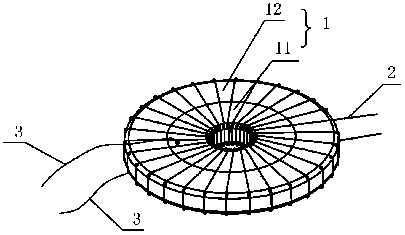
[0028] figure 1 A structural schematic diagram of an adjustable toroidal inductance provided for an embodiment of the present invention, as shown in figure 1 As shown, the controllable toroidal inductance of this embodiment includes: a toroidal magnetoelectric composite element 1 and a coil 2 wound on the toroidal magnetoelectric composite element 1 . Wherein, the annular magnetoelectric composite element 1 includes an annular piezoelectric element 11 and an annular ferromagnetic element 12, and the annular piezoelectric element 11 and the annular ferromagnetic element 12 are arranged concentrically to form a concentric annular magnetoelectric composite structure.
[0029] The concentric arrangement of the annular piezoelectric element 11 and the annular ferromagnetic element 12 can be divided into the following two situations: in the first case, the outer diameter of the annular piezoelectric element 11 is equal to the inner diameter of the annular ferromagnetic element 12, a...
PUM
 Abstract
Description
Claims
Application Information