
Vibrating reed, vibrator, vibration device, sensor, and electronic device

A technology of electronic equipment and vibrating plates, applied in the direction of power oscillators, piezoelectric devices/electrostrictive devices, material selection for piezoelectric devices or electrostrictive devices, etc.

Inactive Publication Date: 2014-04-16
SEIKO EPSON CORP
View PDF8 Cites 4 Cited by
  • Summary
  • Abstract
  • Description
  • Claims
  • Application Information

AI Technical Summary

Problems solved by technology

[0010] However, since the vibrating piece of Patent Document 2 has a structure in which the support portion protrudes laterally or laterally upward on both sides of the base, it is difficult to improve the Q value without increasing the size of the base including the support portion.

Method used


Image

  • Vibrating reed, vibrator, vibration device, sensor, and electronic device
  • Vibrating reed, vibrator, vibration device, sensor, and electronic device
  • Vibrating reed, vibrator, vibration device, sensor, and electronic device

Examples


Embodiment approach )

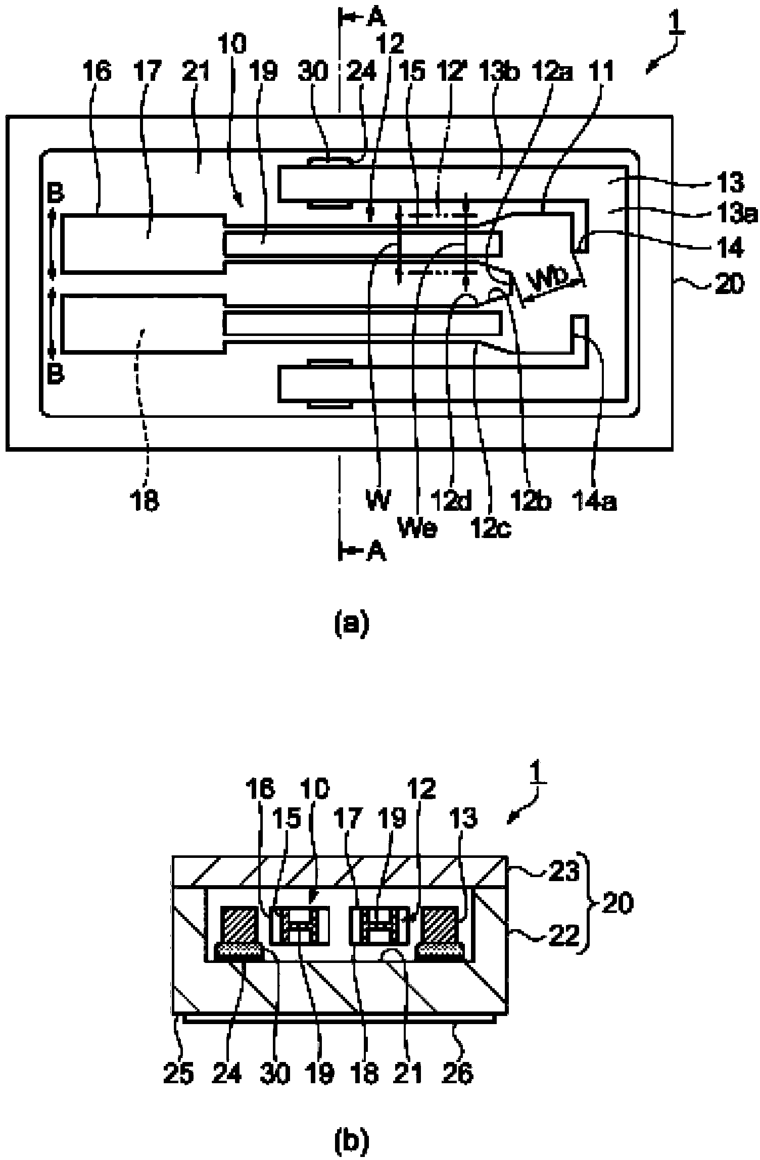
[0042] figure 1 It is a schematic diagram showing the schematic structure of a crystal resonator as a vibration device. figure 1 (a) is a plan view from the cover (cover body) side, figure 1 (b) is along figure 1 The sectional view of the AA line in (a). In addition, in the plan view, the cover is omitted for convenience.

[0043] like figure 1 As shown, the crystal resonator 1 includes a tuning-fork-type crystal resonator reed 10 as a resonator reed that flexibly vibrates in the arrow B direction, and a package 20 that accommodates and fixes the crystal resonator reed 10 therein.

[0044] The quartz vibrating piece 10 has: a base portion 11; a pair of vibrating arms 12 which are integrally formed with the base portion 11 and extend substantially parallel to each other from one end side of the base portion 11; and a support portion 13 which is integrally formed with the base portion 11 and which The other end side of 11 is connected.

[0045] The base 11 of the quartz vi...


PUM


Abstract

The invention provides a vibrating reed, a vibrator, a vibration device, a sensor, and an electronic device. The vibrating reed includes a base having a notch between one end and the other end, a pair of vibrating arms extending from one end of the base in a first direction when in top view, and a support section connected with the other end of the base when in top view, wherein a mechanical resonant frequency f of the vibrating arms is higher than a thermal relaxation frequency f0 of the vibrating arms, and assuming that a closest approach distance between the outer edge of the notch and the outer edge of a crotch section formed between the vibrating arms is a base flexion width Wb, and an arm width of the hypothetical vibrating arm is an effective arm width We, a relationship of Wb>We is satisfied, wherein a cross-sectional shape of the hypothetical vibrating arm along a plane comprising a second direction crossing the first direction and a thickness direction of the vibrating arm is a rectangle, the mechanical resonant frequency of the hypothetical vibrating arm is equal to the mechanical resonant frequency f of the vibrating arm, the thermoelastic loss is equivalent to the thermoelastic loss of the vibrating arm, and the thickness is equal to the thickness of the vibrating arm.

Description

[0001] The patent application of the present invention is a divisional application of the invention patent application with the invention name of "vibration device and electronic equipment", the application date is November 10, 2010, and the application number is "201010542414.9". technical field [0002] The present invention relates to a vibrating piece for bending vibration, a vibrator having the vibrating piece, an oscillator, a sensor, and an electronic device. Background technique [0003] Patent Document 1 discloses a vibrating piece having a base portion and a vibrating arm portion (hereinafter referred to as a vibrating arm) formed to protrude from the base portion, a groove portion is formed in the vibrating arm, and a cut-in portion is formed in the base portion department. [0004] In addition, Patent Document 2 discloses a tuning fork type vibrator (hereinafter referred to as a vibrating piece) having an added value portion (hereinafter referred to as a weight p...

Claims


Application Information

Patent Timeline
Patent Type & Authority Applications(China)
IPC IPC(8): H03H9/21H03H9/15
CPCH01L41/08H01L41/18H03H9/215H03B5/32H03H9/19H03H9/21H03H9/02H01L41/09H01L41/187H10N30/00H10N30/20H10N30/85H10N30/853
Inventor 山田明法
Owner SEIKO EPSON CORP
Learn More