Vacuum valve and closing member that closes the flow path in an airtight manner by linear movement

A technology of linear movement, flow path, applied in the direction of sliding valves, engine components, valve devices, etc.

Inactive Publication Date: 2016-03-02
VAT HLDG AG
View PDF14 Cites 0 Cited by
  • Summary
  • Abstract
  • Description
  • Claims
  • Application Information

AI Technical Summary

Problems solved by technology

[0032] However, even relatively quick and simple replacement of one or more seals or the entire valve closure requires interruption of processing, potentially flooding the chamber with ambient air and the use of replacement parts

Method used


Image

  • Vacuum valve and closing member that closes the flow path in an airtight manner by linear movement
  • Vacuum valve and closing member that closes the flow path in an airtight manner by linear movement
  • Vacuum valve and closing member that closes the flow path in an airtight manner by linear movement

Examples


Embodiment Construction

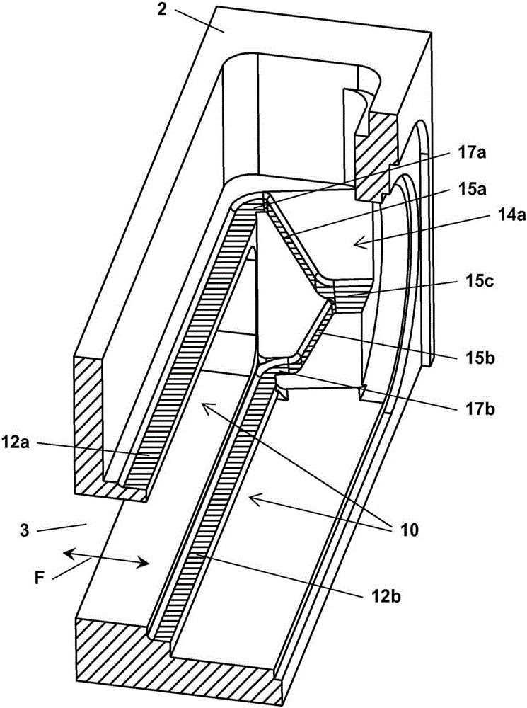
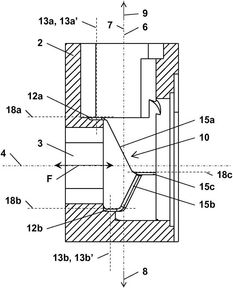
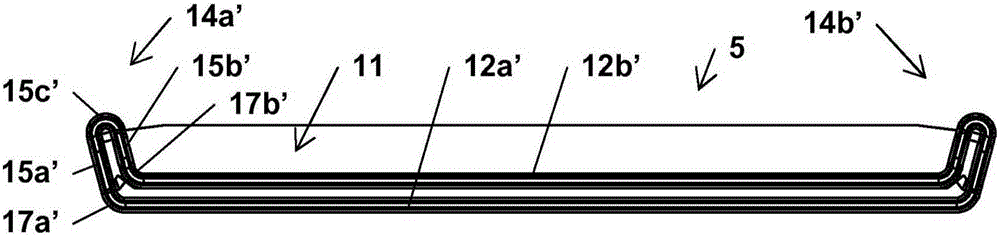
[0124] Figure 1a to Figure 2e , Figure 3a to Figure 3e with Figure 4a to Figure 5e Common exemplary embodiments of vacuum valves or closure members in various states, all as claimed in the present invention, are shown from various views and various levels of detail. Thus, in each case, the groups of figures are described together. according to Figure 2f with Figure 2g variants and based on Figure 4a to Figure 5e Exemplary implementation of and based on Figure 1a to Figure 2e with Figure 3a to Figure 3e The exemplary embodiments differ only in some features, which is part of the reason why only details of the differences between variants and embodiments are given. In part, details of references and features already explained in the previous figures will not be given. Figure 8a with Figure 8b It has been stated in detail in connection with the statements of the prior art.

[0125] Figure 1a to Figure 2e with Figure 3a to Figure 3e A first embodiment of the...


PUM

PropertyMeasurementUnit
Tilt angleaaaaaaaaaa

Abstract

The invention relates to a vacuum valve (1) for closing a flow path (F) in an airtight manner by linear movement, the vacuum valve comprising: a closing member (5), which is linearly displaceable; a second part of the valve housing (2) A sealing surface (10), the first sealing surface closing the opening (3); and, a second sealing surface (11) of the closing member (5), the second sealing surface corresponding to the first sealing surface (10). In the closed position (C), the second sealing surface (11) is in sealing contact with the first sealing surface (10), said contact being pressed against the first sealing surface (10) in the closing direction (8), and the closing member ( 5) Close the opening (3) in an airtight manner. In the area between the opening (3) and the first sealing surface (10), the valve housing (2) comprises a first inclined surface (22) closing the opening (3), and the closing member (5) comprises a first inclined surface parallel to the first inclined surface (22) extends and corresponds to the second inclined surface (23) of the first inclined surface (22). The inclined surfaces ( 22 , 23 ) having an inclination angle ( 24 ) between 3 and 15 degrees relative to the geometrical adjustment axis ( 6 ) are positioned relative to each other such that in the closed position (C) of the closing member ( 5 ), p. The two inclined surfaces ( 23 ) are arranged in parallel positions opposite to the first inclined surface ( 22 ), and have a distance (v) of 0 to 0.6 mm between them.

Description

technical field [0001] The invention relates to a vacuum valve and a corresponding closing member which closes a flow path in an airtight manner by linear movement. Background technique [0002] Said vacuum valve and said closing member are known in particular in the form of delivery valves developed by the company VATVakuumventile AG of Haag, Switzerland under the product designation "MONOVAT series 02 and 03" rectangular plug-in valves. The design and method of operation of such valves are described schematically in eg US 4,809,950 (Geiser) and US 4,881,717 (Geiser). [0003] In general, vacuum valves are known from various embodiments from the prior art, which close a flow path leading through an opening realized in a valve housing in a substantially gas-tight manner. Vacuum gate valves are used in particular in the field of integrated circuit and semiconductor production, which must be carried out in a protected atmosphere, where possible free from contaminating particl...

Claims


Application Information

Patent Timeline
IPC IPC(8): F16K3/314F16K51/02
CPCF16K3/314F16K51/02F16K3/18F16K3/30
Inventor 弗里德里克·盖泽A·纽迈尔B·杜埃里托马斯·布莱哈K·祖默
Owner VAT HLDG AG
Why Eureka
Try Eureka