Spraying device with front heat-sensitive mechanism

A spraying device and heat-sensitive technology, which is applied in fire rescue and other directions, can solve the problems of spray nozzle shape and structure limitation, damage spray, spray head can not be atomized, etc., to achieve diversified spraying forms, improved response ability, and strong fire extinguishing power Effect

Inactive Publication Date: 2014-04-23
韩铁夫
View PDF13 Cites 3 Cited by
  • Summary
  • Abstract
  • Description
  • Claims
  • Application Information

AI Technical Summary

Problems solved by technology

This kind of closed structure is difficult to make an atomizing nozzle, and it has two serious disadvantages: 1. The sealing disc occupies the position of the outlet of the nozzle axis, which hinders the setting of the atomizing core and atomizing nozzle of the nozzle; 2. It is opposite to the outlet of the nozzle when spraying. The thermal element support arm will block and destroy the spray, this structural contradiction restricts the development of closed atomizing nozzles
[0003] Chinese patent application number 99105898.4 discloses a closed nozzle with a heat sensitive element, a rod arm, a hook connector and a sealing ball. The closed nozzle moves the heat sensitive element and the rod arm from the center of the nozzle to the outside of the nozzle , solves the problem that the heat-sensitive element support arm blocks the spray, but still needs to block the nozzle outlet with a hook-shaped connector and a sealing ball, which still severely restricts the shape and structure of the spray nozzle, and the nozzle cannot be used as a multi-nozzle closure Nozzle
Chinese patents with application numbers 95195067.3 and 2005201175195067.3 disclose two closed-spray schemes. In the former, the central nozzle is barely set on the main shaft to face the end of the heat-sensitive element. The central spray is blocked by the heat-sensitive element and the support arm, and the spray effect is poor. It is more suitable for high-pressure liquid spraying; the latter provides a kind of medium and low pressure closed-type fine water mist head structure, which uses oblique nozzles around and sprays to the center to supplement the spray blank caused by the space occupied by the central thermal element
But neither of these two solutions can remove the thermal element and the arm from the center of the nozzle outlet
[0004] Existing fire extinguishing nozzles are generally fixed sprinkler nozzles. Due to the limitation of the structure of the nozzle, the impulse and concentration of the fire extinguishing agent sprayed by it are limited, and the spraying range is relatively close, and the distribution is not uniform. Especially the fine water mist nozzle suffers from these shortcomings. It has a greater impact, which seriously hinders the popularization of medium and low pressure water mist fire extinguishing
A good way to overcome the above shortcomings is to use the rotary spraying method, but the existing rotary spraying devices generally use transmission mechanisms and motors, which are large in size and complex in structure
The patent with application number 200520091525.7 discloses a large-flow nozzle that impacts the rotating water separator with water, but the nozzle can neither atomize, nor is it a closed nozzle that can be opened automatically by temperature sensing

Method used


Image

  • Spraying device with front heat-sensitive mechanism
  • Spraying device with front heat-sensitive mechanism
  • Spraying device with front heat-sensitive mechanism

Examples


Embodiment

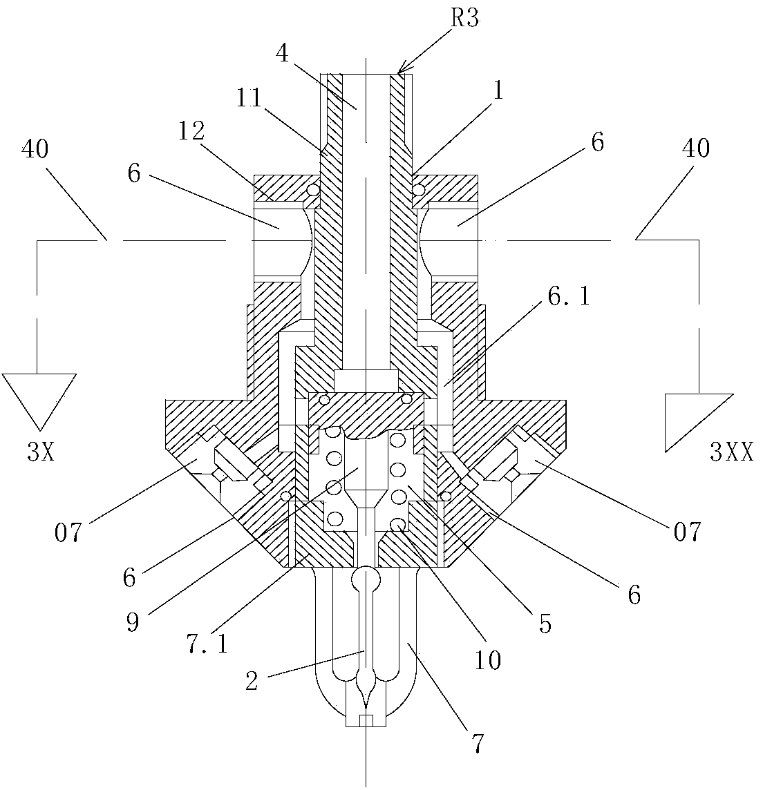
[0027] see figure 2 , and the difference from the existing conventional spraying device with a front thermal mechanism is that the valve body 1 of the normally closed valve R3 is a split-type combined valve body, and the valve body 1 is sleeved by an outer body 12 on the inlet port 4 The intermediate body 11 and the end cap 7.1 are formed. The annular cavity 6.1 formed between the intermediate body 11 and the outer body 12 surrounds the outer periphery of the control cavity 5 formed between the intermediate body 11 and the end cap 7.1. The bracket 7 supports the thermosensitive element 2 , and the thermosensitive element 2 and the spring 10 jointly press against the blocking member 9 to block the passage from the inlet chamber 4 to the control chamber 5 . Grooves are provided on the outer body 12 and the intermediate body 11, and the holes make the control cavity 5 and the annular cavity 6.1 communicate with each outlet cavity 6 arranged around the outer body 12, and each ou...


PUM


Abstract

The invention discloses a spraying device with a front heat-sensitive mechanism and relates to a sprayer for fighting and extinguishing fore. The spraying device is provided with a normally-closed valve and a spraying head and / or a spraying nozzle; the normally-closed valve is provided with a valve body, a blocking piece, a heat-sensitive mechanism and a bracket; the valve body is provided with an inlet cavity, a control cavity and an outlet cavity; the control cavity is arranged at the downstream of the inlet cavity and at the upstream of the outlet cavity, and is positioned at the side of the outlet cavity; the inlet cavity is connected with a pressure flow-spraying source; the outlet cavity is connected with the spraying head and / or the spraying nozzle; the control cavity is provided with the blocking piece; the heat-sensitive mechanism and the bracket are arranged outside the control cavity; the bracket supports the heat-sensitive mechanism; the head part of the blocking piece is sealed between the inlet cavity and the outlet cavity; the valve body of the normally-closed valve is a split and combined type valve body and is provided with an outer sleeve body and a middle body; the outer sleeve body is sheathed and connected to the middle body and an end cover; a ring-shaped cavity is formed between the middle body and the outer sleeve body; the control cavity is formed between the middle body and the end cover; the ring-shaped cavity encloses the periphery of the control cavity and is communicated with the outlet cavity; all the outlet cavities at the upper part of the outer sleeve body are respectively connected with a flow conveying pipe, and all the outlet cavities at the lower part of the outer sleeve body are respectively provided with an atomizing nozzle.

Description

technical field [0001] The invention relates to a spraying device for fire protection, in particular to a closed spraying device with a pre-heat sensitive mechanism capable of quick response and a use method thereof. Background technique [0002] The nozzle used to spray the fire extinguishing agent at the end of the pipeline of the automatic fire extinguishing system determines the working mode and fire extinguishing effect of the fire fighting system. Traditional water mist nozzles, foam nozzles or most fine water mist nozzles are open nozzles that can only open and stop all nozzles at the same time, and they cannot spray independently according to needs. The traditional sprinkler head is a low-pressure closed sprinkler head, but it has a large amount of water, large water droplets, and large water pollution. It is not suitable for oil, gas, and electrical fires, and needs to be improved. In the existing closed nozzles, the heat-sensitive mechanism is set in the outlet di...

Claims


Application Information

Patent Timeline
Patent Type & Authority Applications(China)
IPC IPC(8): A62C31/02A62C37/08
Inventor 韩铁夫
Owner 韩铁夫
Why Eureka
Try Eureka