

Dispensing devices with pre-disposed heat-sensitive mechanism and its use method
A spraying device and heat-sensitive technology, which is applied in fire rescue and other directions, can solve the problems of spray nozzle shape and structure limitation, damage spray, spray head can not be atomized, etc., to achieve diversified spraying forms, improved response ability, and strong fire extinguishing power Effect
- Summary
- Abstract
- Description
- Claims
- Application Information
AI Technical Summary
Problems solved by technology
Method used
Image

Examples
Embodiment 1
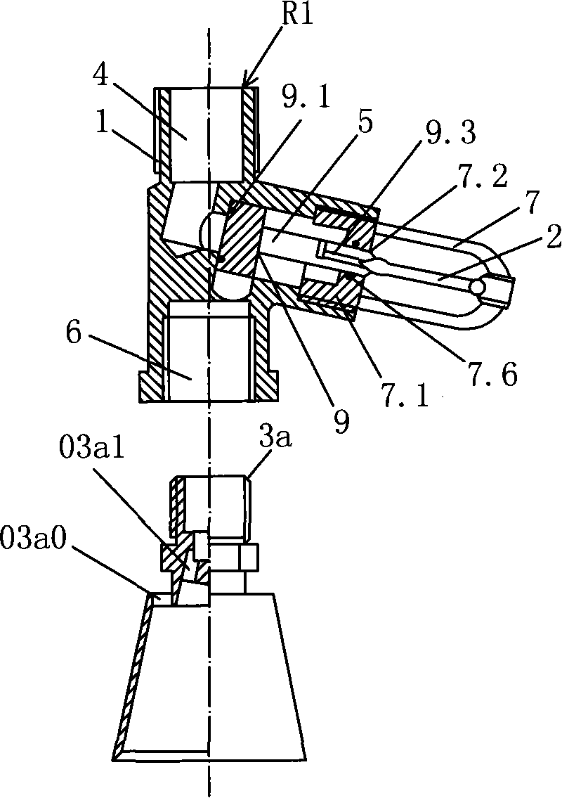
[0033] see figure 1 , the present invention has a spraying device with a pre-heat sensitive mechanism, which is provided with a normally closed valve R1 and a spray head 3a. The mouth 6 is directly threaded with the nozzle 3a.
[0034]The valve body 1 is provided with an inlet chamber 4, a control chamber 5 and an outlet chamber 6, the control chamber 5 is located between the inlet chamber 4 and the outlet chamber 6, and the control chamber 5 is located on the side of the outlet chamber 6, that is, the axis of the control chamber 5 An included angle is formed with the axis of the outlet cavity 6 (the included angle may be less than, equal to or greater than 90 degrees). The thermosensitive mechanism is an independent thermosensitive element 2, which is a thermosensitive glass bulb (also can be a fusible alloy component, etc.), and the thermosensitive element 2 is exposed in the atmosphere. The outer port of the control chamber 5 is provided with an end cover 7.1, and the end...
Embodiment 2
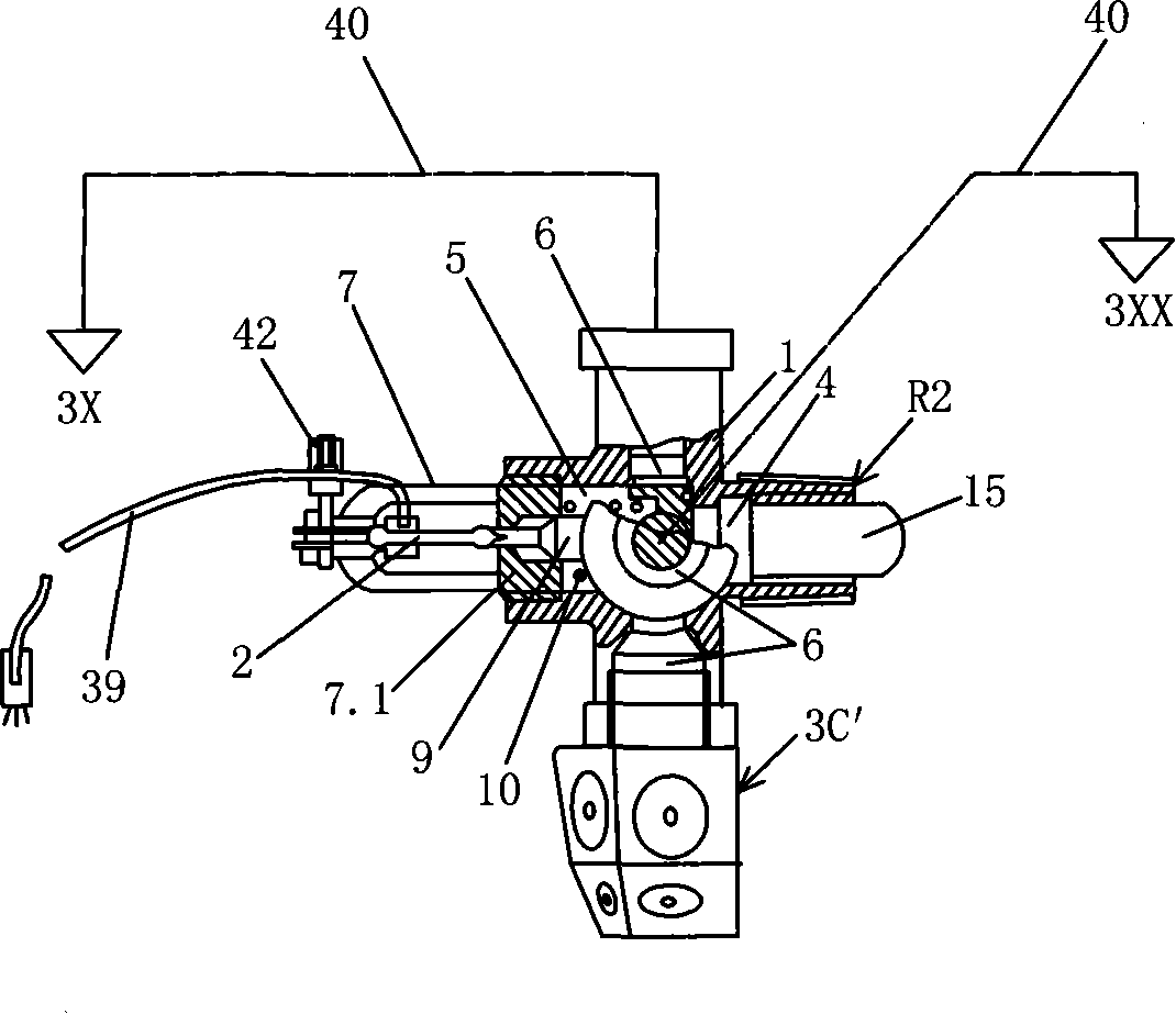
[0037] see figure 2 , similar to Embodiment 1, the difference is that the valve body 1 of the normally closed valve R2 is a multi-way body, the valve body 1 is provided with 4 outlet chambers 6 (the number of outlet chambers 6 can be set according to needs), the inlet chamber 4 and the outlet chamber 6 is vertical, and the control cavity 5 is set on the side of the outlet cavity 6. A filter 15 (can be provided as required) is provided in the inlet chamber 4 . A spring 10 is arranged between the blocking piece 9 and the end cover 7.1, one end of the spring 10 is in contact with the end cover 7.1, and the other end of the spring 10 is in contact with the blocking piece 9, and the spring 10 is helpful for the compression and reset of the blocking piece 9. An outlet port 6 at the lower part of the valve body 1 is directly connected to a nozzle 3c' (the nozzle 3c' is a fine water mist side wall nozzle, and can also be other types of nozzles), and the other outlet ports 6 are conn...
Embodiment 3
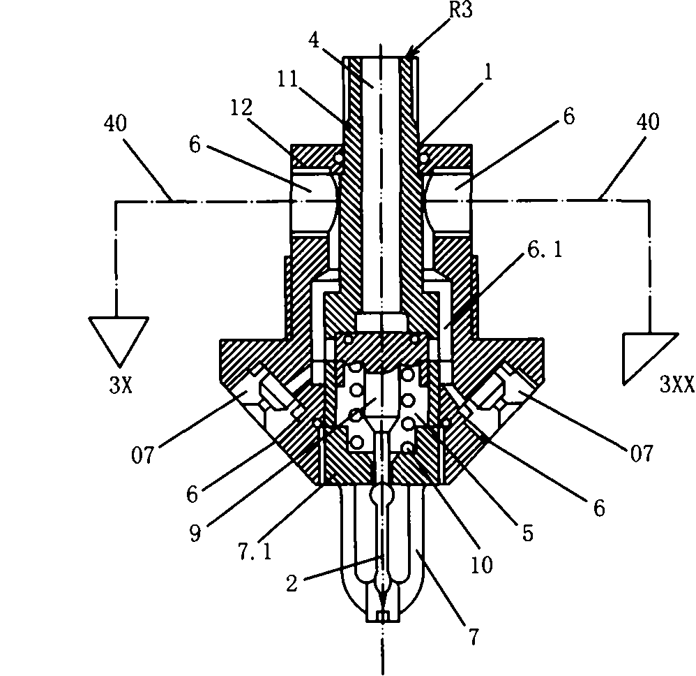
[0039] see image 3 , similar to Example 1, the valve body 1 of the normally closed valve R3 is a split-type combined valve body, and the valve body 1 is composed of an outer body 12 sleeved on the intermediate body 11 provided with the inlet cavity 4 and the end cover 7.1. The annular cavity 6.1 formed between the intermediate body 11 and the outer body 12 surrounds the outer periphery of the control cavity 5 formed between the intermediate body 11 and the end cap 7.1. The bracket 7 supports the thermosensitive element 2 , and the thermosensitive element 2 and the spring 10 jointly press against the blocking member 9 to block the passage from the inlet chamber 4 to the control chamber 5 . Grooves are provided on the outer body 12 and the intermediate body 11, and the holes make the control cavity 5 and the annular cavity 6.1 communicate with each outlet cavity 6 arranged around the outer body 12, and each outlet cavity 6 on the upper part of the outer body 12 is respectively ...
PUM
 Abstract
Description
Claims
Application Information