
Device for automatically correcting circular degree

An automatic correction and roundness technology, applied in metal processing equipment, forming tools, manufacturing tools, etc., can solve problems such as unstable roundness correction quality, low production efficiency, and difficulty in controlling rotating parts.

Active Publication Date: 2014-04-23
惠州安特科技工业有限公司
View PDF6 Cites 9 Cited by
  • Summary
  • Abstract
  • Description
  • Claims
  • Application Information

AI Technical Summary

Problems solved by technology

[0003] In the prior art, the roundness correction of the round tube part is usually to put the round tube part on a rotating mandrel of the stamping die, fix it on the mandrel and cooperate with the dial block and be driven by the dial block fixing rod and the dial block. The roundness correction is carried out by the method of intermittently rotating the rotating parts. This method can correct the roundness more accurately, but because this method is a single-action form, the mold needs to work six times continuously to complete the roundness correction of a part. Production The efficiency is low and the effect of the shifting block on the rotating part makes it difficult to control the stop of the rotating part, thus causing problems such as unstable roundness correction quality

Method used


Image

  • Device for automatically correcting circular degree
  • Device for automatically correcting circular degree
  • Device for automatically correcting circular degree

Examples


Embodiment Construction

[0022] In order to facilitate the understanding of those skilled in the art, the present invention will be further described in detail below with reference to the drawings and embodiments.

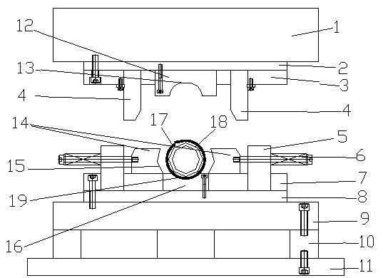
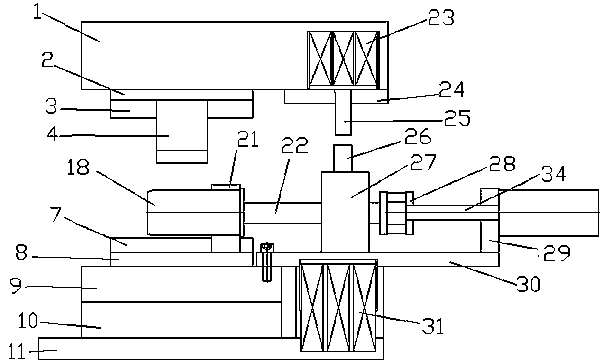
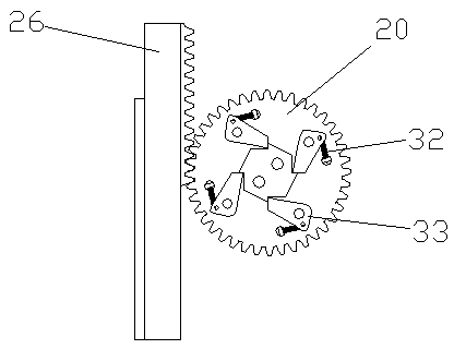
[0023] Such as figure 1 , 2 , 3, 4, and 5, the automatic roundness correction device of the present invention includes a fixed plate 3 and a concave template 7, the vertical correction punch 12 is installed on the fixed plate 3, and the concave template 7 is equipped with Mandrel fixing seat 21, rotatable mandrel 18 is installed on the mandrel fixing seat 21, and mandrel 18 is positioned at the right below of vertical correction punch 12, and on described fixing plate 3 and concave template 7, install behind mandrel 18 There is a rotary positioning mechanism. The bottom of the concave template 7 is provided with a die backing plate 8, a lower mold base 9, a die foot 10, and a die foot backing plate 11 in sequence. In the rotary positioning mechanism, a gear 20 is arranged in a gear box 2...


PUM


Abstract

The invention provides a device for automatically correcting the circular degree. The device comprises a fixing plate (3) and a cavity die plate (7); the fixing plate (3) is provided with a vertical correction core die (12); the cavity die plate (7) is provided with a core shaft fixing seat (21) which is provided with a rotatable core shaft (18); the core shaft (18) is located under the vertical correction core die (12); rotating positioning mechanisms are arranged on the fixing plate (3) and the cavity die plate (7) and behind the core shaft (18). According to the device for automatically correcting the circular degree, gears and racks which are arranged in the rotating positioning mechanisms are matched with each other to stably control a directional shaft to drive the core shaft to rotate and accordingly the circular degree of a circle tubular component is accurate and accordingly the production process is effectively simplified and the production rate is improved.

Description

technical field [0001] The invention relates to an automatic roundness correction device for round tubular parts. Background technique [0002] Round tubular parts are widely used in people's daily life. Round tubular parts are usually bent into wave shapes from flat blank profiles, and then the wave shaped profiles are bent into round tubes. The roundness of the bent round tubes is poor, and the roundness requirements are higher For high-precision products, roundness correction must be performed in all directions around the round tube part. [0003] In the prior art, the roundness correction of the round tube part is usually to put the round tube part on a rotating mandrel of the stamping die, fix it on the mandrel and cooperate with the dial block and be driven by the dial block fixing rod and the dial block. The roundness correction is carried out by the method of intermittently rotating the rotating parts. This method can correct the roundness more accurately, but becau...

Claims


Application Information

Patent Timeline
IPC IPC(8): B21D3/00B21D37/10
Inventor 张明华王胜宇李会宁
Owner 惠州安特科技工业有限公司
Learn More