Grip bottle opener
A bottle opener and grip technology, applied in the direction of flange-type cap disassembly, etc., can solve the problems of unergonomic, troublesome operation, and no fundamental improvement in ease of operation and comfort.
- Summary
- Abstract
- Description
- Claims
- Application Information
AI Technical Summary
Problems solved by technology
Method used
Image
Examples
Embodiment 1
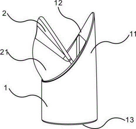
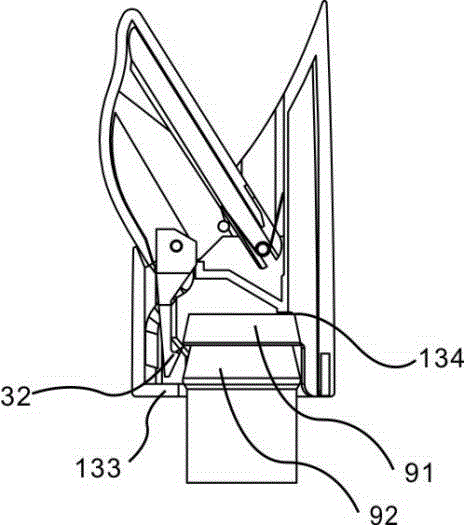
[0030] Refer below Figure 1~Figure 5 A grip bottle opener of one embodiment of the present invention will be described.
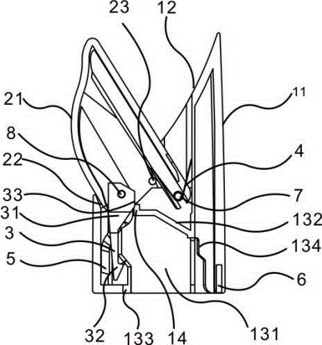
[0031] Such as figure 1 , figure 2 As shown, the grip bottle opener includes a holding mechanism 1, which is a hollow through structure, which includes an upper cylindrical holding portion 11, a limiting portion 12 inside the holding portion 11, and an introduction portion 13 in the lower portion. The holding portion 11 It can be held by human hands, the limiting part 12 is an inclined surface, and satisfies 0°
[0032] The driving mechanism 2 is installed in the hollow cavity inside the limiting part 12, and is flexibly connected with the holding mechanism 1 through the first rotating shaft 7. The first rotating shaft 7 is located at the bottom of the hollow cavity inside the limiting part 12, close to the holding On the si...
Embodiment 2
[0036] Refer below Figure 1~Figure 5 A grip bottle opener of one embodiment of the present invention will be described.
[0037] Such as figure 1 , figure 2 As shown, the grip bottle opener includes a holding mechanism 1, which is a hollow through structure, which includes an upper cylindrical holding portion 11, a limiting portion 12 inside the holding portion 11, and an introduction portion 13 in the lower portion. The holding portion 11 It can be held by human hands, the limiting part 12 is an inclined surface, and satisfies 0°
[0038] The introduction part 13 includes a guide part 131 and a limi...
Embodiment 3
[0046] This embodiment mainly describes the installation structure of the holding mechanism and the driving mechanism.
[0047] Such as Figure 6 As shown, the holding mechanism 1 is provided with a U-shaped shaft hole 15 and an elastic pressing block 16 at the bottom of the hollow cavity inside the limiting part 12. When the driving mechanism 2 is installed in the hollow cavity inside the limiting part 12, the first The rotating shaft 7 enters the shaft hole 15 and is pushed down by the elastic pressing block 16, so that the mechanism can be connected without fasteners such as screws.
[0048] Such as Figure 7 As shown, the lower part of the driving mechanism 2 is provided with a shaft hole 24, a shaft hole 25 and a shaft hole 26, and the first rotating shaft 7, the torsion spring shaft 23 and the second rotating shaft 8 are installed respectively.
PUM
 Abstract
Description
Claims
Application Information
 - R&D
- Intellectual Property
- Life Sciences
- Materials
- Tech Scout
- Unparalleled Data Quality
- Higher Quality Content
- 60% Fewer Hallucinations
Browse by: Latest US Patents, China's latest patents, Technical Efficacy Thesaurus, Application Domain, Technology Topic, Popular Technical Reports.
© 2025 PatSnap. All rights reserved.Legal|Privacy policy|Modern Slavery Act Transparency Statement|Sitemap|About US| Contact US: help@patsnap.com


