LED stereoscopic area light source

A technology of three-dimensional surface and LED light bar, which is applied in the field of optical lighting, can solve the problems of not being able to obtain three-dimensional lighting effects and general three-dimensional effects, and achieve the effect of meeting the requirements of different viewing distances and flexible structure

Inactive Publication Date: 2014-04-23
青岛卓英社科技股份有限公司
View PDF2 Cites 0 Cited by
  • Summary
  • Abstract
  • Description
  • Claims
  • Application Information

AI Technical Summary

Problems solved by technology

This kind of three-dimensional painting technology has a simple structure, but the three-dimensional effect is relatively general, which largely depends on the viewing angle of the observer. If the viewing an...

Method used


Image

  • LED stereoscopic area light source
  • LED stereoscopic area light source
  • LED stereoscopic area light source

Examples


Embodiment 1

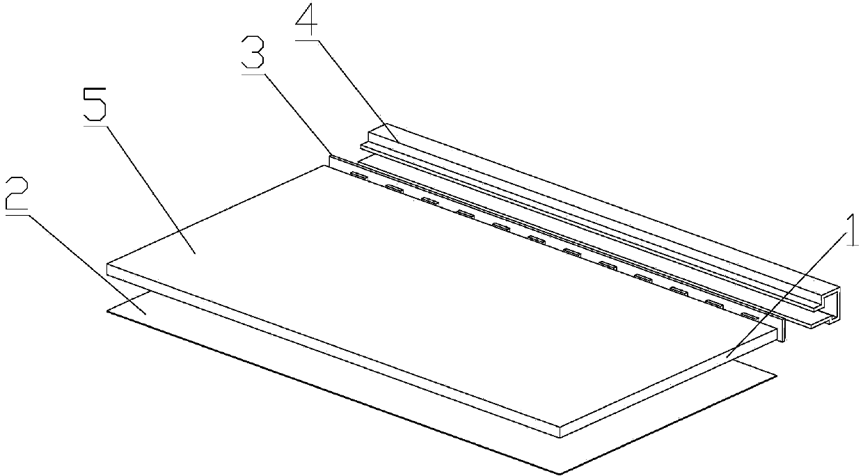
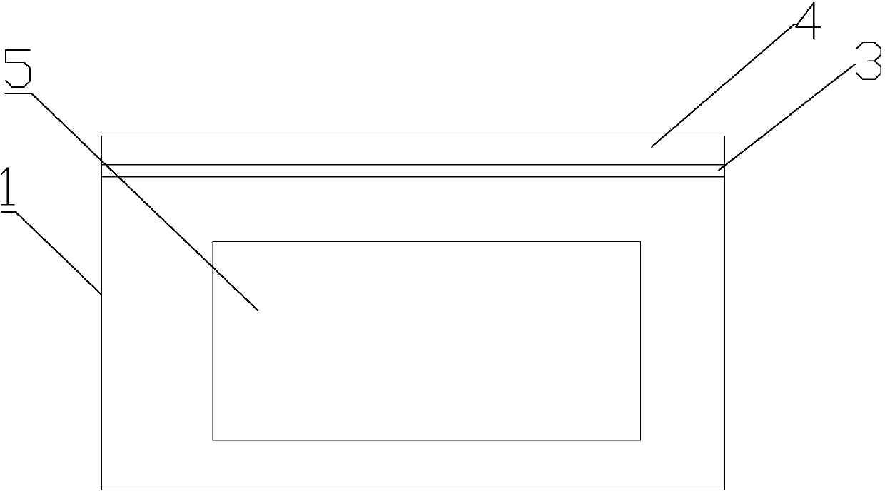
[0018] Such as figure 1 and figure 2 Shown:

[0019] An LED three-dimensional surface light source, comprising an LED light bar 3, a cooling bracket 4 and a light guide plate 1, the light guide plate 1 includes a light input end and a light output end, the LED light bar 3 is arranged on the edge of the light guide plate, and one end of the LED light bar 3 is set It is the light incident end of the light guide plate, the light source enters the light from the side of the light guide plate, and the cooling bracket 4 is arranged on the light incident end of the light source to overlap with the LED light bar 3; one side of the light guide plate 1 is provided with a light guide point, and the point propagation, to realize the light emitting perpendicular to the surface of the light guide plate, the side of the light guide plate 1 opposite to the set light guide point is the light emitting surface of the light guide plate 1, and the light emitting surface of the light guide plate ...

Embodiment 2

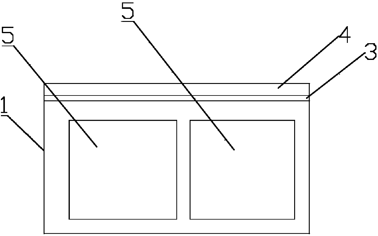
[0022] Such as figure 1 and image 3 Shown:

[0023] An LED three-dimensional surface light source, comprising an LED light bar 3, a cooling bracket 4 and a light guide plate 1, the light guide plate 1 includes a light input end and a light output end, the LED light bar 3 is arranged on the edge of the light guide plate, and one end of the LED light bar 3 is set It is the light incident end of the light guide plate, the light source enters the light from the side of the light guide plate, propagates through the light guide point, and realizes the light emitting perpendicular to the surface of the light guide plate, and the cooling bracket 4 is arranged at the light incident end of the light source to overlap with the LED light bar 3; One side of the light guide plate 1 is provided with a light guide point, the opposite side of the light guide plate 1 is the light-emitting surface of the light guide plate 1, and the light-emitting surface of the light guide plate 1 is provided...


PUM


Abstract

An LED stereoscopic area light source comprises an LED light bar, a radiating support, and a light guide plate. The LED stereoscopic area light source is characterized in that the light guide plate comprises an incident end and an emergent end, the LED light bar is disposed at the edge of the light guide plate, the end, which the LED light bar is arranged at, is the incident end of the light guide plate, the radiating support is disposed at the incident end of a light source and in lap joint with the LED light bar, one side of the light guide plate is provided with light guide points, the other side, opposite to the light guide points, of the light guide plate is an emergent side of the light guide plate, the emergent side of the light guide plate is provided with a stereoscopic pattern which is made on the light guide plate by carving, and the surface of the stereoscopic pattern is provided with a coating. The LED area light source capable of mapping stereoscopic diagrams is designed by combining the traditional area light source, the stereo technology and the nano technology; the LED area light source has the effect of stereoscopic lighting, is capable of emitting light and is also ornamental.

Description

technical field [0001] The invention belongs to the technical field of optical lighting and relates to an LED surface light source, in particular to an LED three-dimensional surface light source. Background technique [0002] Three-dimensional picture technology is a technology with high ornamental value. At present, most three-dimensional picture technology uses grating materials combined with corresponding patterns, and uses the refraction effect of grating to achieve three-dimensional visual effects. It can also be called grating three-dimensional picture technology. There is also a three-dimensional picture technology that combines the grating three-dimensional picture technology with optical technology, and the three-dimensional picture can realize the effect of light by setting a simple optical illuminant behind the grating three-dimensional picture. This three-dimensional painting technology has a simple structure, but the three-dimensional effect is more general, and...

Claims


Application Information

Patent Timeline
IPC IPC(8): F21S2/00F21V13/02F21Y101/02F21K9/20F21Y115/10
Inventor 王恩辉王涛王温暖徐晓凯
Owner 青岛卓英社科技股份有限公司
Why Eureka
Try Eureka