A drop point detection device and detection method for ointment for cables

A detection device and ointment technology, applied in the field of cable materials, can solve problems such as visual fatigue and insecurity, and achieve the effects of low labor intensity, accurate recording, and simple device

Inactive Publication Date: 2016-04-06
XINXIANG UNIV
View PDF5 Cites 0 Cited by
  • Summary
  • Abstract
  • Description
  • Claims
  • Application Information

AI Technical Summary

Problems solved by technology

However, most of the current inspection equipment uses open flame heating to measure, which is very unsafe; in addition, during the inspection, inspectors need to determine the temperature value through continuous visual observation, so it is easy to cause visual fatigue

Method used


Image

  • A drop point detection device and detection method for ointment for cables
  • A drop point detection device and detection method for ointment for cables
  • A drop point detection device and detection method for ointment for cables

Examples


Embodiment 1

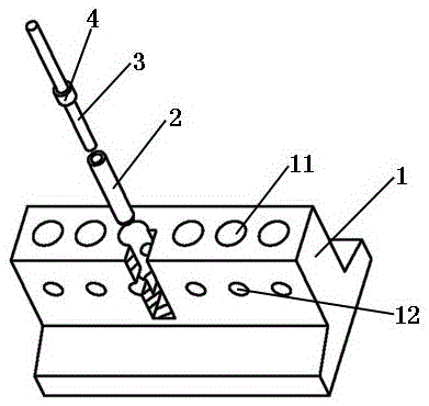
[0024] please see figure 1 ,refer to Figure 4 and Figure 5 , a drop point detection device for cable ointment is characterized in that it includes a housing 1, a heating device 16 located inside the housing, and a power connection line; the upper part of the housing is in the shape of a cuboid, and the vertical direction on the cuboid has A plurality of container lumens 11 that are not connected to each other. The horizontal direction on the cuboid has a plurality of observation holes 12 that are corresponding to the container cavity and are not connected to each other. The corresponding observation holes are connected to the container cavity. The cavity and the observation hole are both straight holes, and the observation hole runs through the front and rear sides of the cuboid in the horizontal direction; on the orthographic projection of the front side of the cuboid, the observation hole is located in the middle and lower part of the corresponding container cavity; the h...

Embodiment 2

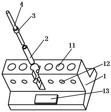
[0026] please see figure 2 ,refer to Figure 4 and Figure 5 , a drop point detection device for cable ointment, characterized in that it includes a housing 1, a heating device 16 located inside the housing, a display and setting device 18, a power connection line, and a display on the housing and the operation panel 13; the top of the housing is in the shape of a cuboid, the vertical direction on the cuboid has a plurality of chambers 11 that are not connected to each other, and the horizontal direction on the cuboid has a plurality of observation chambers that are corresponding to the chambers and are not connected to each other. Hole 12, the corresponding observation hole is connected with the container cavity, the container cavity and the observation hole are straight holes, and the observation hole runs through the front and rear sides of the cuboid in the horizontal direction; on the orthographic projection of the front side of the cuboid , the observation hole is loc...

Embodiment 3

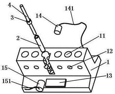
[0028] please see image 3 ,refer to Figure 4 and Figure 5 , a drop point detection device for cable ointment, is characterized in that it includes a housing 1, a heating device 16 positioned inside the housing, a display and setting device 18, a power connection line, a temperature detection device 19, a computing and Control device 17, signal transmitting device 14 and signal receiving device 15 located outside the housing, display and operation panel 13 located on the housing; the upper part of the housing is in the shape of a cuboid, and the vertical direction on the cuboid has a plurality of non-communicating holding tubes Cavity 11, the horizontal direction on the cuboid has a plurality of observation holes 12 corresponding to the container cavity and not communicating with each other, the corresponding observation holes are connected to the container cavity, and both the container cavity and the observation hole are straight holes , the observation hole runs through...


PUM


Abstract

The invention belongs to the technical field of cable materials, and in particular relates to a drop point detection device for optical cable or cable ointment. Cuboid shape, the cuboid has multiple cavities that are not connected to each other, and the horizontal direction on the cuboid has multiple observation holes that correspond to the cavities and are not connected to each other, and the corresponding observation holes are connected to the cavities Yes, both the container cavity and the observation hole are straight holes, and the observation hole runs through the front and rear sides of the cuboid in the horizontal direction; on the orthographic projection of the front side of the cuboid, the observation hole is located in the middle and lower part of the corresponding container cavity; heating The device is wrapped around each lumen. The invention also discloses a detection method. The invention has the following main beneficial effects: the device is simple, the operation is simple, and it is safer and more environmentally friendly; the test method is more scientific and reasonable, and the records are more accurate; the time spent by inspectors is less, and the labor intensity is lower.

Description

technical field [0001] The invention belongs to the technical field of cable materials, and in particular relates to a drop point detection device and detection method for an optical cable or cable ointment. Background technique [0002] Dropping point is the thermal performance index of petroleum filling paste, which refers to the temperature at which the ointment is heated to the first drop of oil under specified conditions. The drop point indicates the degree to which the ointment can withstand the temperature during use, and the drop point is generally higher than the use temperature. The dropping point is not as high as possible, too high dropping point may affect the low-temperature performance of the ointment, resulting in reduced cone penetration, increased density and so on. At present, GB / T4929 "Method for Determination of Dropping Point of Lubricating Grease" is generally used in China to determine the dropping point. However, most of the current inspection equi...

Claims


Application Information

Patent Timeline
Patent Type & Authority Patents(China)
IPC IPC(8): G01N25/04
Inventor 马超连黎明姬清华李亚敏刘贵敏
Owner XINXIANG UNIV
Why Eureka
Try Eureka