
Ship propulsion vertical permanent magnet motor

A permanent magnet motor, vertical technology, applied to synchronous motors with stationary armatures and rotating magnets, electromechanical devices, electrical components, etc. Requirements, low reliability of permanent magnet motors, etc., to achieve the effect of increasing the cross section, increasing the air gap flux density and power density, and reducing tooth expansion

Active Publication Date: 2016-02-24
CRRC YONGJI ELECTRIC CO LTD
View PDF7 Cites 1 Cited by
  • Summary
  • Abstract
  • Description
  • Claims
  • Application Information

AI Technical Summary

Problems solved by technology

[0003] The present invention solves the problems of low operational reliability, limited capacity expansion, low air-gap magnetic density, low power density, low structural strength, difficulty in meeting operating requirements in temperature rise, and difficulty in adapting to ship propulsion systems in existing permanent magnet motors. To solve the problem of inclined operating conditions, a vertical permanent magnet motor for ship propulsion is provided

Method used


Image

  • Ship propulsion vertical permanent magnet motor
  • Ship propulsion vertical permanent magnet motor
  • Ship propulsion vertical permanent magnet motor

Examples


Embodiment Construction

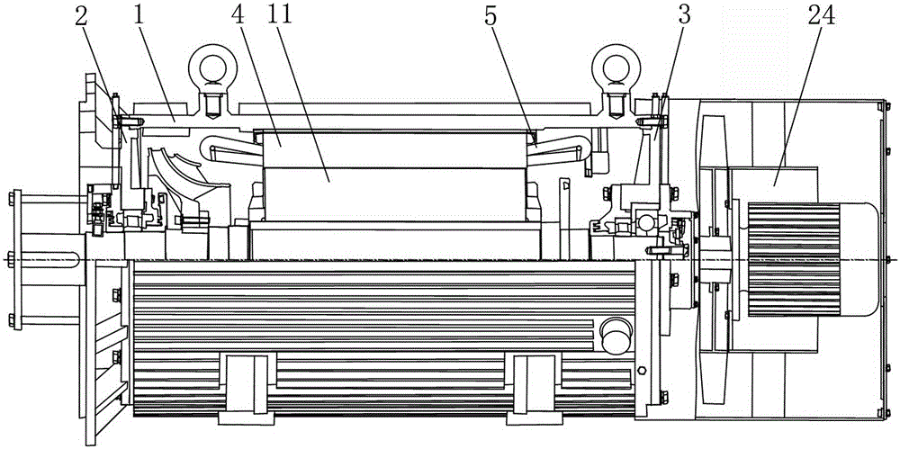
[0014] Ship propulsion vertical permanent magnet motor, including machine base 1, front end cover 2, rear end cover 3, stator structure, rotor structure, three-bearing structure, and air-cooled structure; wherein, front end cover 2 is fixedly assembled on the front surface of machine base 1 ;The rear end cover 3 is fixedly assembled on the rear end surface of the base 1;

[0015] The stator structure includes a stator core 4 and a stator coil 5; the stator core 4 is fixedly assembled on the inner surface of the base 1; the stator coil 5 is embedded on the stator core 4;

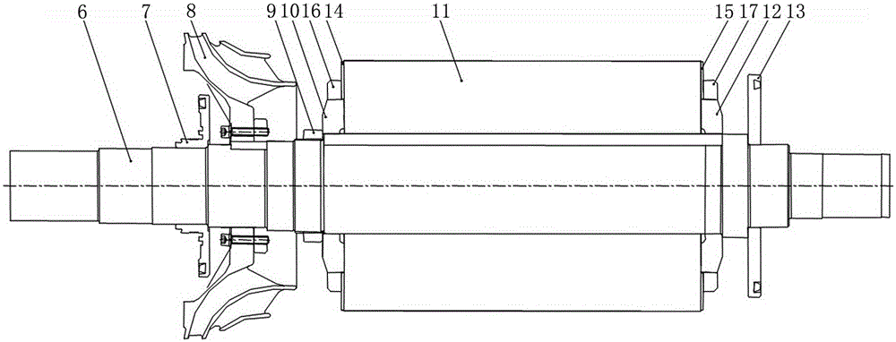
[0016] The rotor structure includes a rotating shaft 6, an inner sealing ring 7, a fan 8, a round nut 9, a first rotor pressure ring 10, a rotor core 11, a second rotor pressure ring 12, a balance plate 13; an inner sealing ring 7, a fan 8, The round nut 9, the first rotor pressure ring 10, the rotor core 11, the second rotor pressure ring 12, and the balance plate 13 are fixedly assembled on the outer surfac...


PUM


Abstract

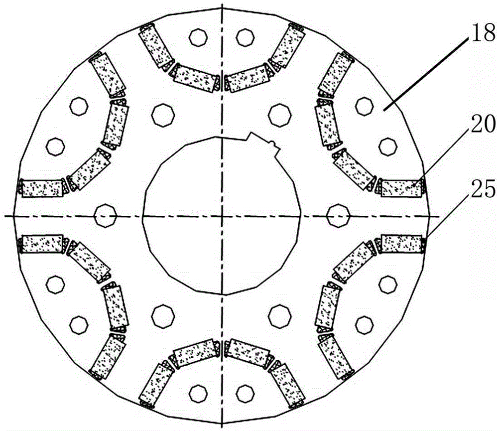
The invention relates to a permanent-magnetic motor, in particular to a ship propelling-type permanent-magnetic motor, which aims at solving the problems of the existing permanent-magnetic motor that the reliability in running is low, the capacity expansion is limited, the air-pore magnetic density is low, the power density is low, the structural strength is low, the temperature increasing is difficult for meeting the running requirement, and the oblique running working condition of a ship propelling system is difficult to satisfy. The ship propelling-type permanent-magnetic motor comprises a stand, a front end cover, a rear end cover, a stator structure, a rotor structure, a three-bearing structure and an air cooling structure; the rotor structure comprises a rotating shaft, an inner seal ring, a fan, a circular nut, a first rotor pressure ring, a rotor iron core, a second rotor pressure ring and a balance disc; the outer side surface of the first rotor pressure ring and the outer side surface of the second rotor pressure ring are respectively and uniformly provided with N outer teeth which are equally spaced along the circumferential direction; the outer ring of the end surface of the rotor iron core is circumferentially provided with N groups of magnetic steel grooves at intervals; each group of magnetic steel grooves consists of four magnetic steel grooves which are symmetrically distributed in a U shape. The ship propelling-type permanent-magnetic motor is applicable to a ship propelling system.

Description

technical field [0001] The invention relates to a permanent magnet motor, in particular to a ship propulsion vertical permanent magnet motor. Background technique [0002] Permanent magnet motors are widely used in ship propulsion systems because of their advantages such as simple structure, small size, light weight, low loss, and high efficiency. Practice has shown that the existing permanent magnet motors generally have the following problems due to their own structure limitations: First, the rotor pressure rings of the existing permanent magnet motors all adopt circular rotor pressure rings. The crimping area of ​​the circular rotor pressure ring is small. On the one hand, the tooth expansion of the rotor core is larger, which leads to the lower reliability of the motor. On the other hand, the permanent magnet section cannot be increased under the same volume ( That is, the magnetic steel groove cannot be increased), which leads to the limitation of the capacity expansio...

Claims


Application Information

Patent Timeline
Patent Type & Authority Patents(China)
IPC IPC(8): H02K21/14H02K1/27H02K1/28H02K7/08H02K9/04
Inventor 刘荣强贾喜勤孙德强倪伟吴楠罗慧强
Owner CRRC YONGJI ELECTRIC CO LTD
Learn More