

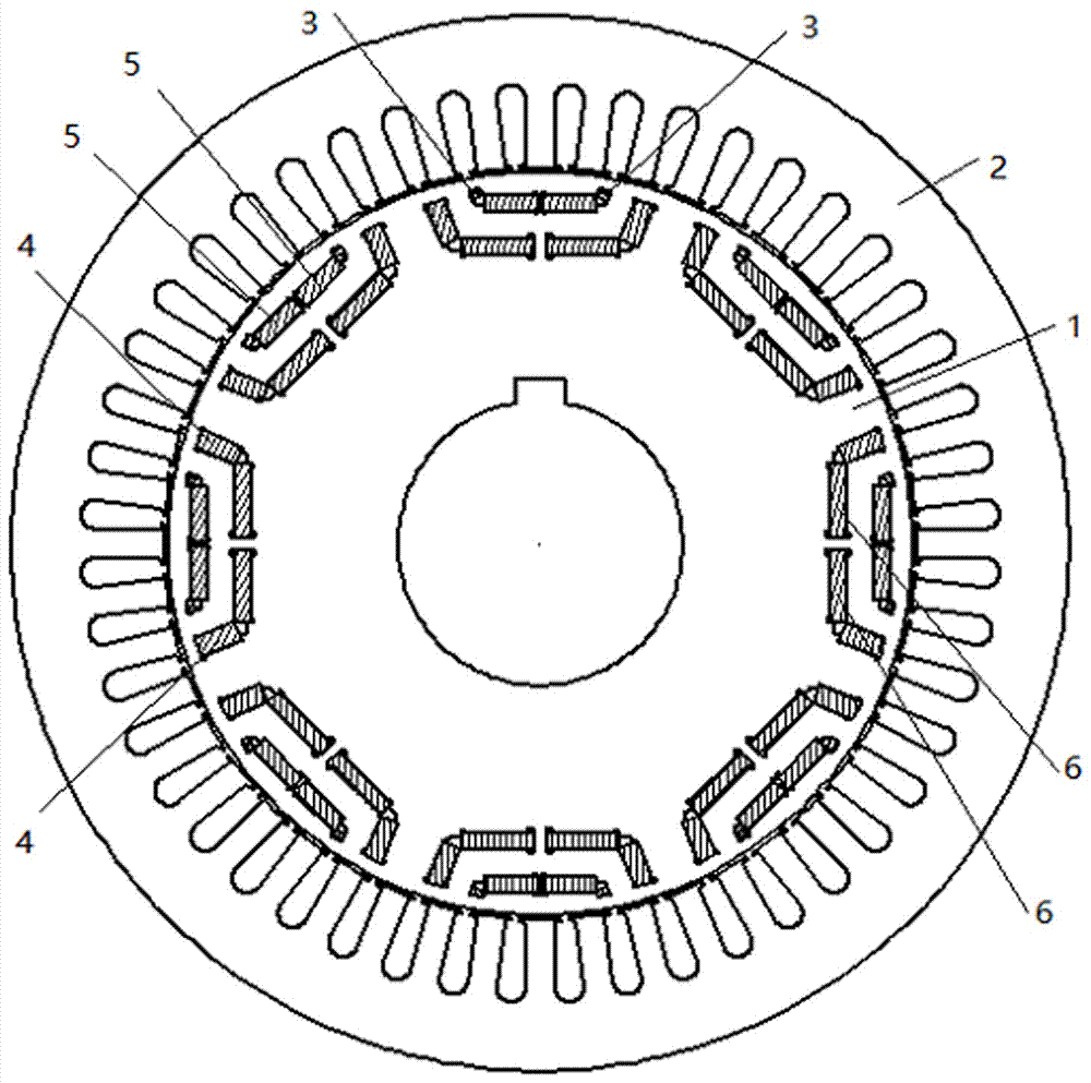
High-torque permanent-magnet motor
A permanent magnet motor, high torque technology, applied in the direction of magnetic circuits, electrical components, electromechanical devices, etc., can solve the problems of increased rotor damage, low power density, and reduced motor efficiency, so as to improve the air gap flux density and power density , The distribution shape of the magnetic flux is reasonable, and the effect of reducing the possibility of damage
- Summary
- Abstract
- Description
- Claims
- Application Information
AI Technical Summary
Problems solved by technology
Method used
Image

Examples
Embodiment Construction
[0038] The technical solutions of the present invention will be clearly and completely described below in conjunction with the accompanying drawings. Apparently, the described embodiments are some of the embodiments of the present invention, but not all of them. Based on the embodiments of the present invention, all other embodiments obtained by persons of ordinary skill in the art without making creative efforts belong to the protection scope of the present invention.
[0039] In the description of the present invention, it should be noted that unless otherwise specified and limited, the terms "installation", "connection" and "connection" should be understood in a broad sense, for example, it can be a fixed connection or a detachable connection. Connected, or integrally connected; it can be directly connected, or indirectly connected through an intermediary, and it can be the internal communication of two elements. Those of ordinary skill in the art can understand the specifi...
PUM
 Abstract
Description
Claims
Application Information