
filter

A technology of filter and filter body, which is applied in the filter field and can solve problems such as complicated production

Inactive Publication Date: 2016-01-06
MAHLE INT GMBH
View PDF12 Cites 0 Cited by
  • Summary
  • Abstract
  • Description
  • Claims
  • Application Information

AI Technical Summary

Problems solved by technology

The filter is therefore also assembled from a number of separate parts, so its manufacture is more complicated

Method used


Image

  • filter
  • filter
  • filter

Examples


Embodiment Construction

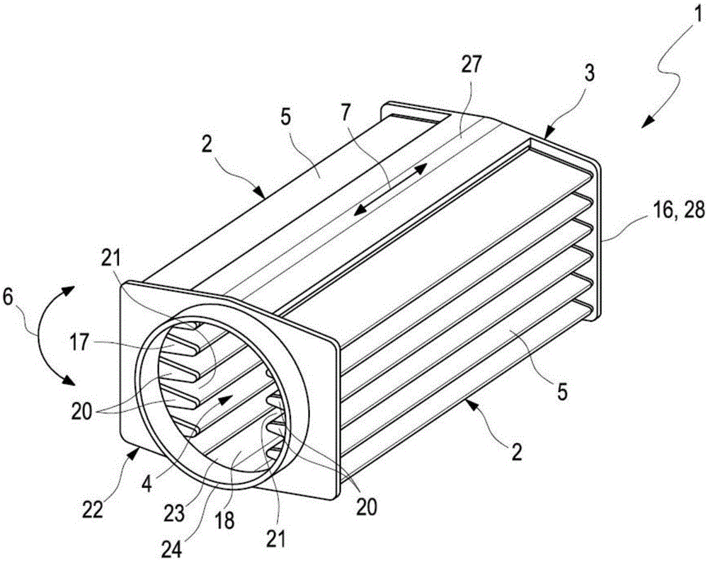
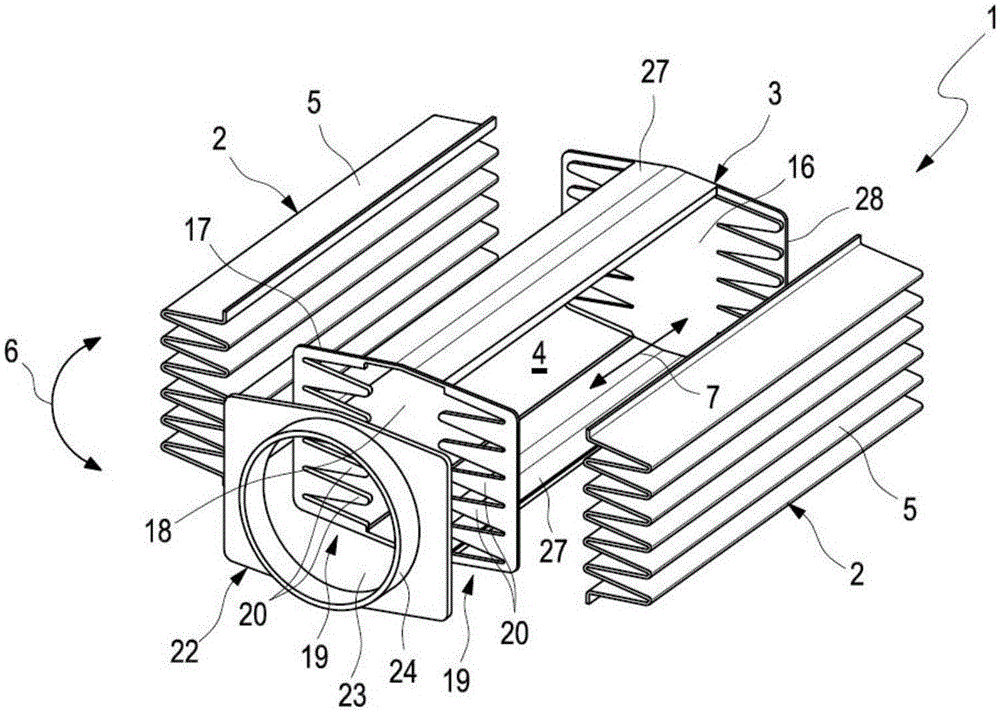
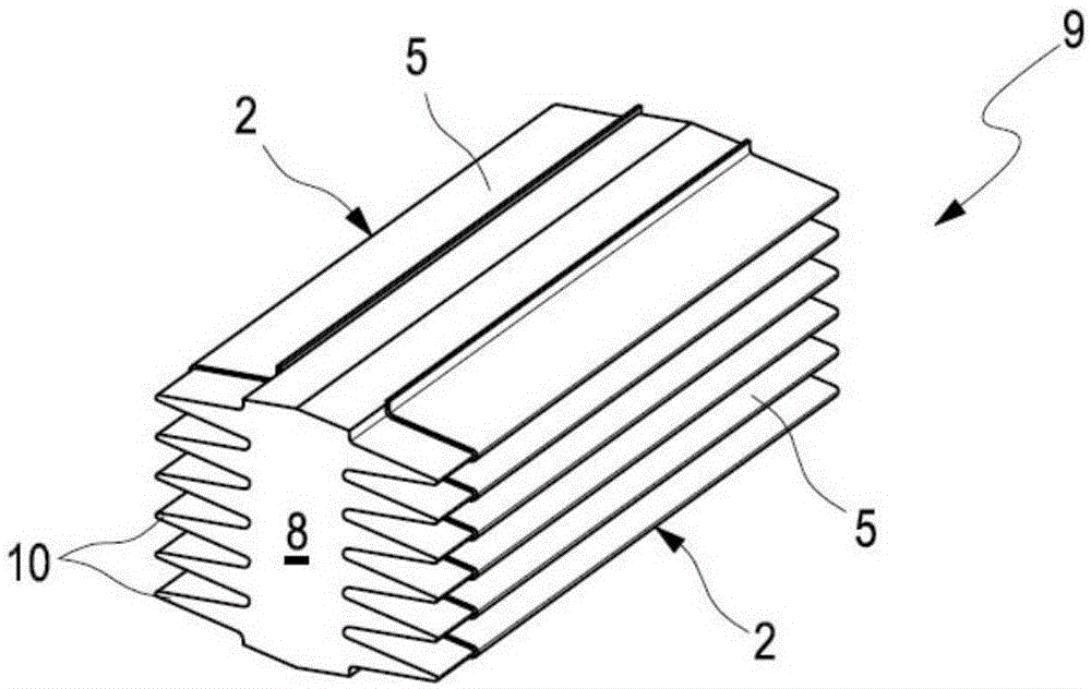
[0041] refer to Figure 1-19 , the filter 1 includes a filter body 2, a support structure 3 and an inner space 4, the filter 1 is preferably a gas filter, especially an air filter. Filter 1 is thus a cavity filter. The filter body 2 consists of a single-layer or multi-layer filter material 5 , preferably a foldable filter material in the exemplary embodiment shown here. The support structure 3 serves for the positioning of the filter body 2 and thus fixes the spatial position of the filter body 2 . The inner space 4 is surrounded by the support structure 3 and the filter 2 in the circumferential direction 6 indicated by the double arrow. In addition, the inner space 4 is divided at the end by the supporting structure 3 along the axis direction 7 indicated by the double arrow, and the Figure 1-16 The end is located on the side away from the direction of the observer. The support structure 3 is an injection molded part and is molded onto the filter body 2 so that the suppor...


PUM


Abstract

The invention relates to a filter (1), especially a filter for a gas filter device of a motor vehicle fresh air system, which comprises at least one filter body (2) made of filter material (5), one for a support structure (3) on which the filter body (2) is positioned and an interior space (4), which is surrounded in the circumferential direction (6) by the support structure (3) and at least one filter body (2), The filter body (2) is axially bonded by the support structure (3). A simple, low-cost construction is obtained if the support structure (3) is molded onto at least one filter body (2) and forms a plastic block.

Description

technical field [0001] The invention relates to a filter, in particular to a filter for a gas filter, preferably an air filter of a ventilation system of a motor vehicle, which has the features of the preamble of claim 1 . Background technique [0002] EP2292311A1 discloses a filter with several filter bodies formed from filter material and a support structure for positioning the filter bodies. Furthermore, the filter has an inner space which is surrounded in the circumferential direction by the support structure and the filter body and is separated axially. In known filters, each filter body consists of filter plates, which are produced independently of the other filters. Furthermore, in known filters, the support structure is formed by an appropriate combination of materials and assembly of frame parts. The production of known filters is thus relatively complicated. [0003] DE 10 2004 005 904 A1 discloses a filter comprising at least three filter bodies consisting of a...

Claims


Application Information

Patent Timeline
Patent Type & Authority Patents(China)
IPC IPC(8): B01D46/24B01D46/52B01D46/00
CPCB01D46/2403B01D46/0015B01D46/521B01D46/522B01D46/523B01D2265/04B01D2267/30B01D2267/40B01D2271/02B01D2271/022B01D2271/027B01D2275/206B01D2275/207B01D46/58B01D46/52B60H3/06B01D2201/12
Inventor 斯特凡·比巴劳夫·布劳恩斯文·亚历山大·凯泽
Owner MAHLE INT GMBH
Learn More