

Camera
A camera and motor vehicle interior technology, applied in the field of cameras, can solve the problems of each tooth colliding with each other, and achieve the effect of reliable function
- Summary
- Abstract
- Description
- Claims
- Application Information
AI Technical Summary
Problems solved by technology
Method used
Image

Examples
Embodiment Construction
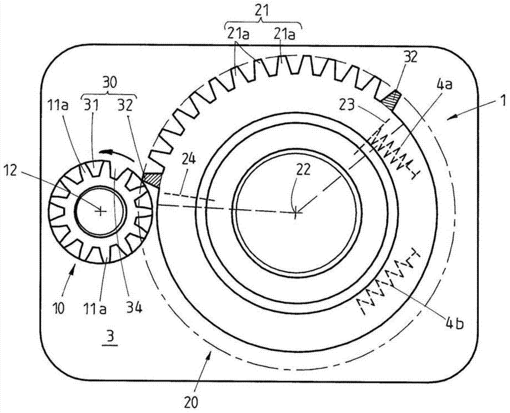
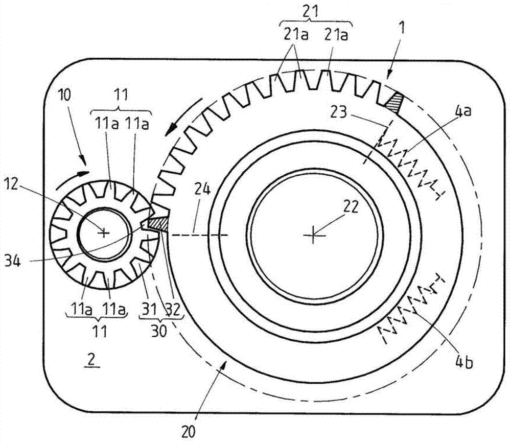
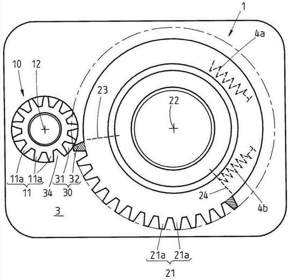
[0021] in accordance with Figure 1 to Figure 3 In the exemplary embodiment shown, a possible gear unit 1 of a video camera is shown, which has a drive element 10 and an output element 20 . The two parts 10 , 20 are arranged displaceably relative to each other. The drive element 10 is designed as a toothed wheel 10 which is mounted rotatably about a first axis 12 . Here, the drive element 10 has a toothing 11 which interacts with a toothing 21 of the driven element 20 , which in figure 2 As shown in , the toothing 21 of the output element 20 is shown in this figure as meshing with the toothing 11 of the driver 10 , which will be explained below.
[0022] All toothed elements 11a of the drive element 10 are identical in terms of their geometry. In contrast, the toothing 21 of the output element 20 has two outer teeth 32 which are designed differently from the toothing 21 a of the output element 20 in terms of their geometry. Teeth 32 are shown hatched. as in Figure 4 As...
PUM
 Abstract
Description
Claims
Application Information