Spring lock for secondary spring

A spring lock, air spring technology, applied in the direction of spring, spring/shock absorber, spring/shock absorber design characteristics, etc., can solve problems such as large expenses

Inactive Publication Date: 2014-04-30
SIEMENS AG OESTERR
View PDF8 Cites 2 Cited by
  • Summary
  • Abstract
  • Description
  • Claims
  • Application Information

AI Technical Summary

Problems solved by technology

This causes huge overhead

Method used


Image

  • Spring lock for secondary spring
  • Spring lock for secondary spring
  • Spring lock for secondary spring

Examples


Embodiment Construction

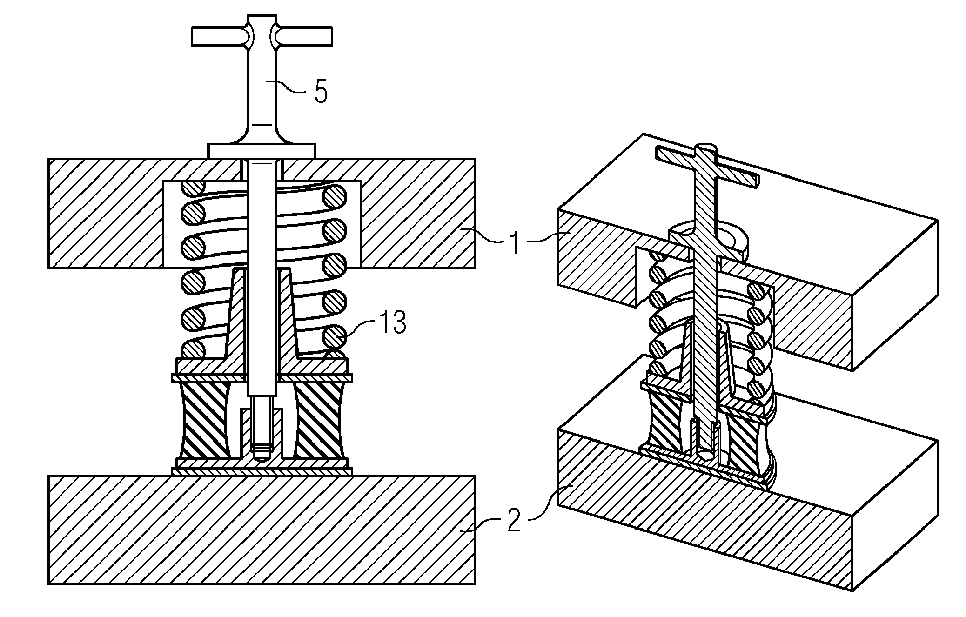
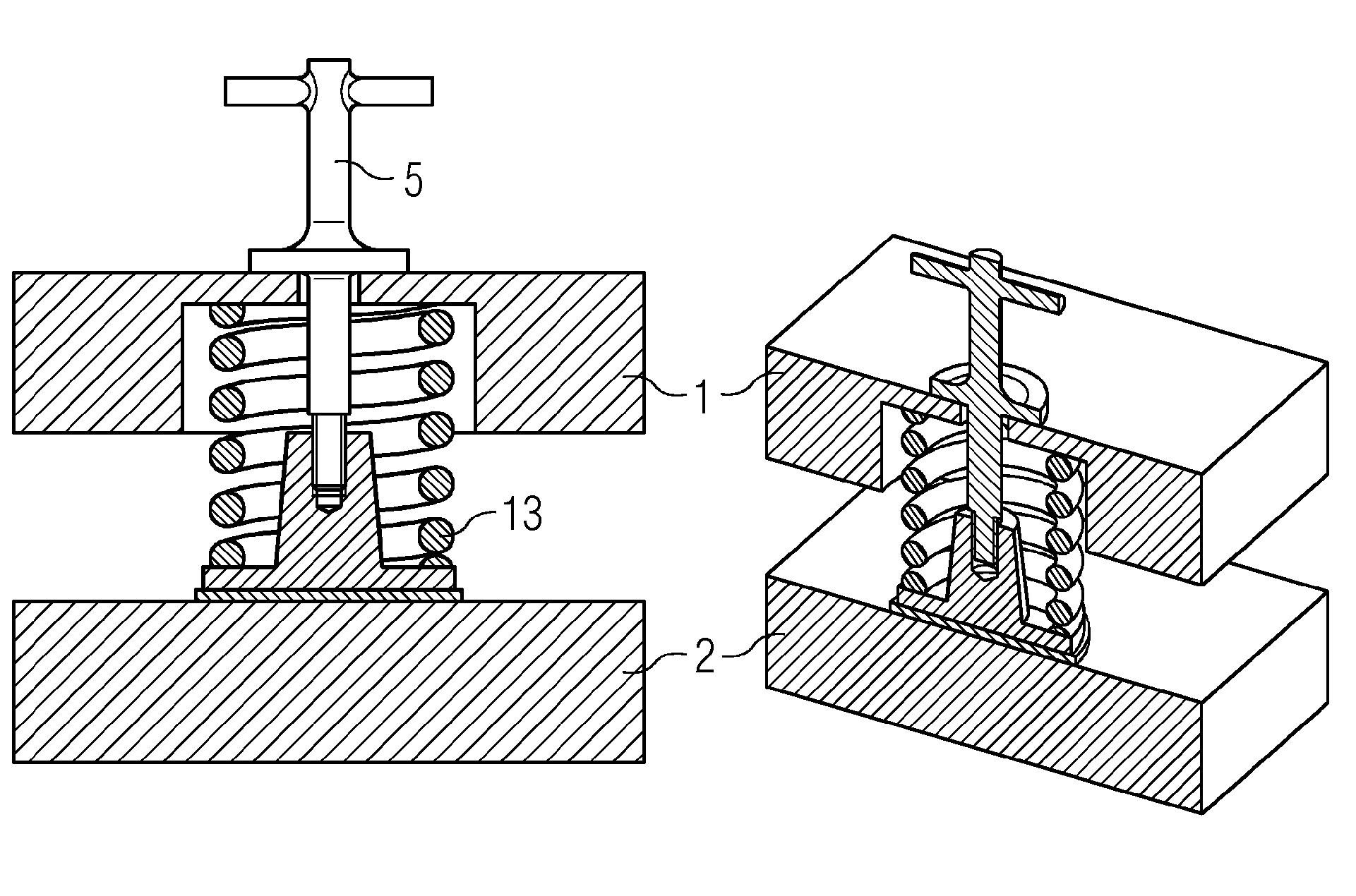
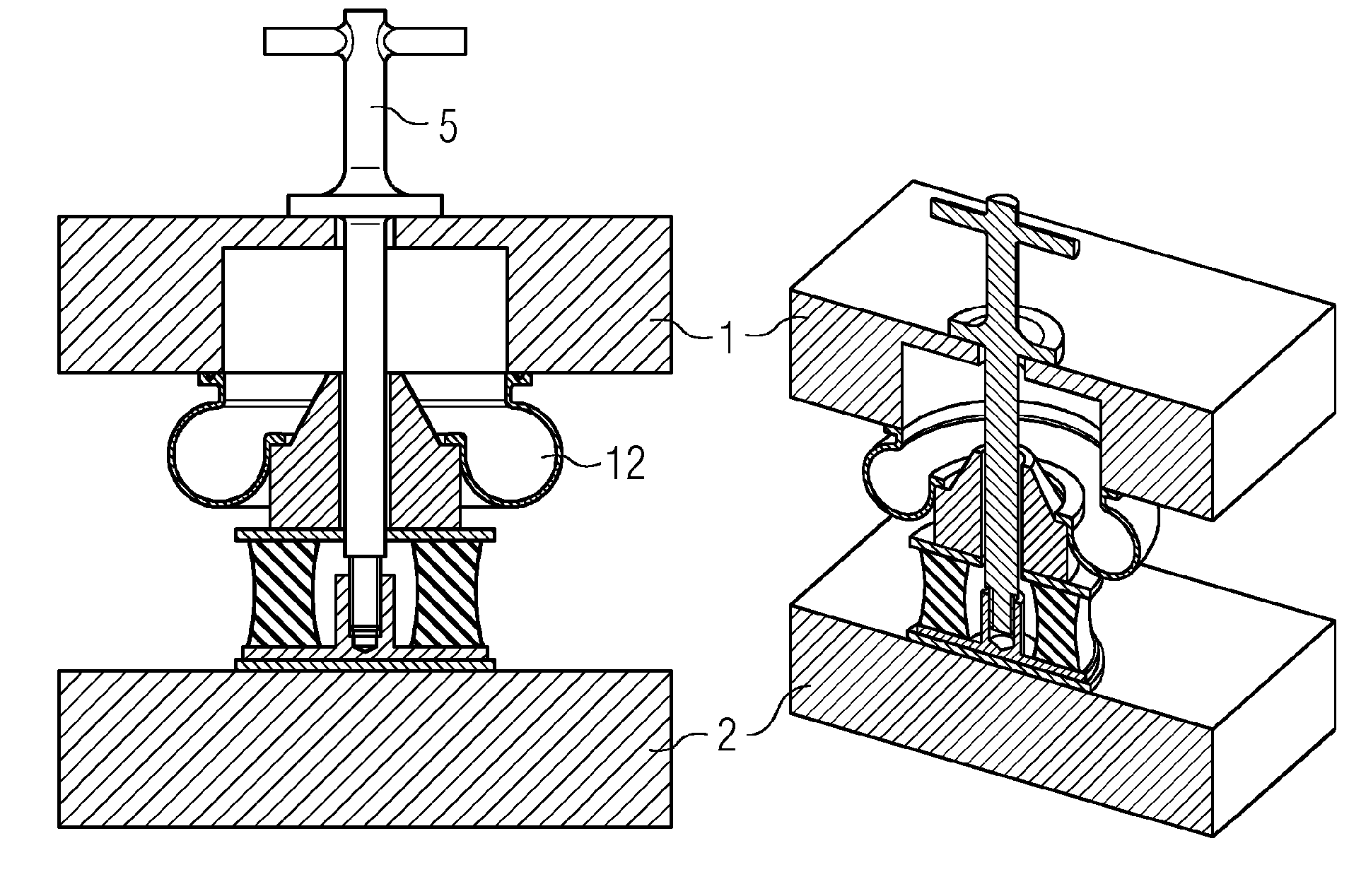
[0021] according to figure 1 The illustration in FIG. 2 shows a section of a body 1 and an undercarriage 2 , that is to say a chassis or a bogie, of a rail vehicle. A conical spring is arranged as secondary spring 3 between the two. To this end, it should be noted that the number of secondary springs 3 between the body 1 and the chassis 2 can vary, typically two or four springs, for example.

[0022] In the carriage body 1 , above each secondary spring 3 there is provided a lockable recess in the operating state, through which recess a cylindrical shaft 6 of the locking element 5 passes in the mounted state. In the carriage 1 itself, the locking element 5 protrudes with the upper end of its cylindrical handle 6 and the transverse handle 7 out of the floor and is thus clearly visible. It can thus be checked very quickly whether the secondary spring 3 is locked or has been released again after the installation work has been completed.

[0023] At its lower end, the cylindrica...


PUM


Abstract

The invention relates to a spring lock for a secondary spring which is arranged between the car body and the underframe of a rail vehicle, in which a spring locking element (5) is provided which in the mounted state is supported on the car body (1) and projects through a cutout and is connected to the secondary spring (3, 12, 13) in such a way that it is prevented from extending. This facilitates the mounting of anti-wear washers (10) under the secondary spring (3, 12, 13) considerably.

Description

technical field [0001] The invention relates to a latch for a secondary spring arranged between a car body and an undercarriage of a rail vehicle. Background technique [0002] For rail vehicles, wheel wear can lead to a reduction in the height of the car position. [0003] Therefore, when entering a station, the following situation can occur: the level of the floor arranged in the carriage is lower than the level of the floor of the station. Due to the level difference between the station and the edge of the floor of the carriage, a step may form in the transition region between the rail vehicle and the station. These steps represent a great safety risk for the passengers, so according to the prior art this loss of height due to wheel wear is compensated by raising the wagon relative to the undercarriage, chassis or bogie. For this, wear pads in the form of metal or plastic shims are pushed under the secondary springs supporting the carriage. [0004] In order to install...

Claims


Application Information

Patent Timeline
Patent Type & Authority Applications(China)
IPC IPC(8): B61F5/08B61F5/10
CPCB61F5/06B61F5/10B61F5/08B61F5/14F16F1/371F16F2230/0041
Inventor D.克雷尤维格
Owner SIEMENS AG OESTERR
Why Eureka
Try Eureka