
Robot controller and robot system

A robot and controller technology, applied in the direction of program control manipulator, electrical program control, comprehensive factory control, etc., can solve the problems of insufficient synchronization accuracy and cannot be further improved

Inactive Publication Date: 2014-05-07
YASKAWA DENKI KK
View PDF7 Cites 2 Cited by
  • Summary
  • Abstract
  • Description
  • Claims
  • Application Information

AI Technical Summary

Problems solved by technology

[0005] However, conventional robot controllers and robot systems provided with the robot controllers have insufficient synchronization accuracy between controlled groups, and thus cannot be further improved in making controlled groups perform coordinated actions in a synchronized manner with each other.

Method used


Image

  • Robot controller and robot system
  • Robot controller and robot system
  • Robot controller and robot system

Examples

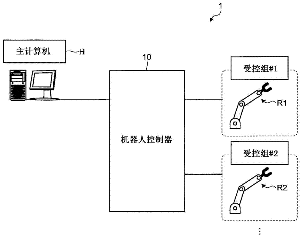

Embodiment Construction

[0025] Embodiments of the robot controller and the robot system disclosed herein will be described below with reference to the accompanying drawings. It is to be noted that the embodiments are not limited to those described below.

[0026] In the description below, each of a plurality of components of the same type is assigned a symbol with a suffix in the form of a numeral followed by a hyphen. However, when these components are described as a whole, they are described by using only the symbol without using a suffix in the form of a numeral followed by a hyphen in some cases.

[0027] First, will use figure 1 An example of the overall configuration of the robot system 1 will be described. figure 1 is a diagram showing an example of the overall configuration of the robot system 1 according to the embodiment.

[0028] like figure 1 As shown, the robot system 1 is provided with a host computer H, a robot controller 10 and a plurality of controlled groups. The host computer ...


PUM


Abstract

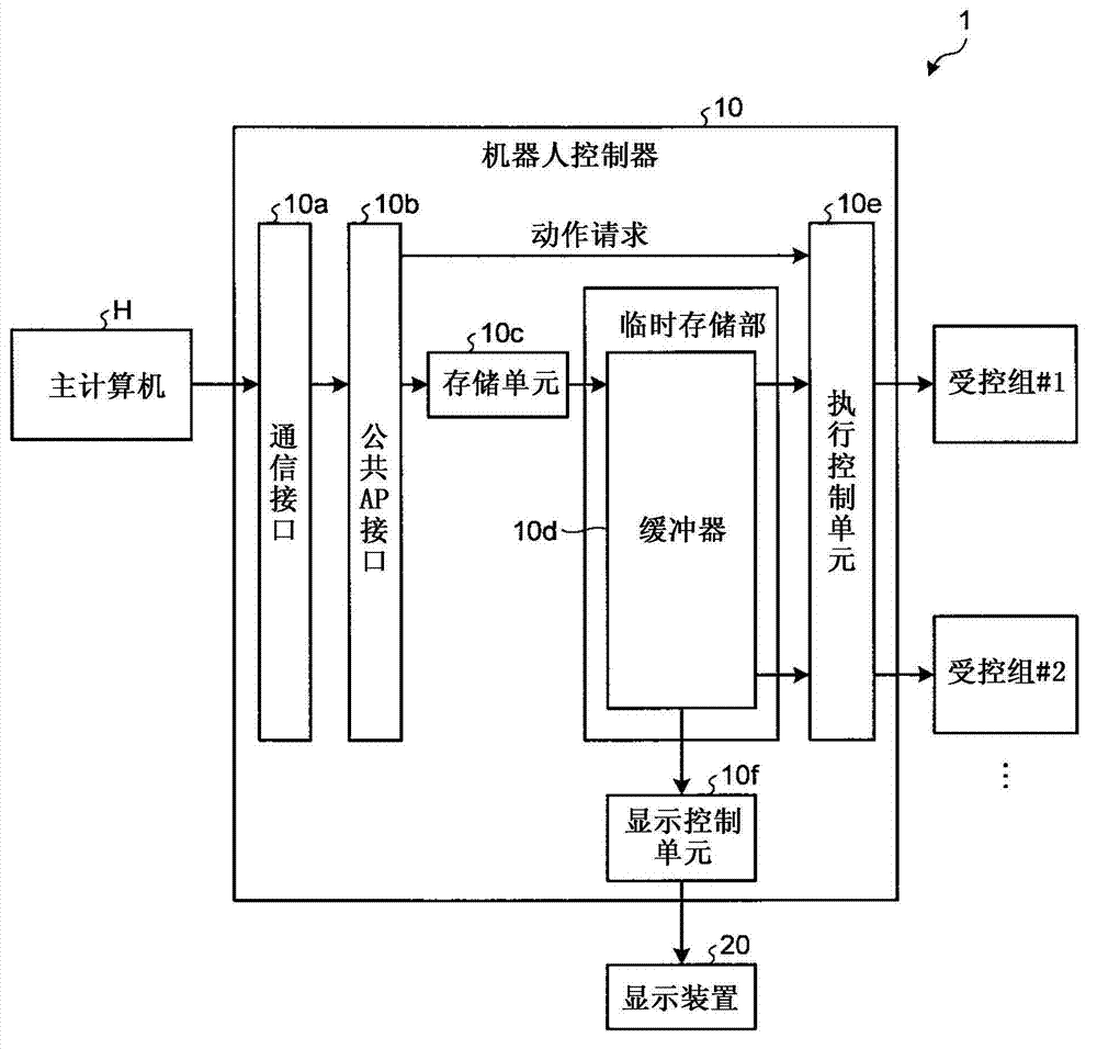
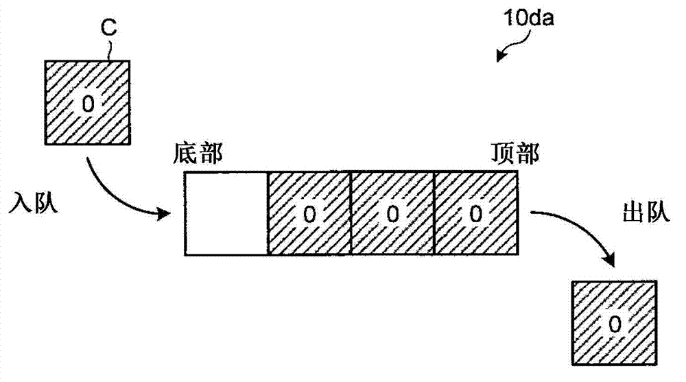
The invention relates to a robot controller and a robot system. The robot controller includes queues, a storage unit, and an execution control unit. The queues are provided for respective controlled groups serving as controlled units. The storage unit stores therein instructions directed to the respective controlled groups, one at a time, from a bottom end of each of the queues. When having accepted a predetermined operation request, the execution control unit simultaneously fetches the instructions directed to the controlled groups, one for each of the controlled groups at a time, from tops of the queues, and makes all of the controlled groups simultaneously start the operations based on such instructions. If there is any controlled group to which no corresponding instruction exists, the storage unit stores therein a no-operation instruction (NOP). If the fetched instruction is the no-operation instruction (NOP), the execution control unit keeps the controlled group from operating until an instruction is fetched next time.

Description

technical field [0001] Embodiments discussed herein relate to robotic controllers and robotic systems. Background technique [0002] There are conventionally known robot controllers, each of which is connected to a plurality of robots in communication with each other and controls the action of each robot individually (for example, refer to Japanese Patent Application Laid-Open No. H3-182908). [0003] Such a robot controller has, for example, a first-in-first-out buffer allocated to each robot, and can operate the robots in parallel by sequentially reading commands related to each robot stored in each buffer and executing the commands. [0004] Objects controlled by the robot controller may include peripheral devices of the robot and the like in addition to the robot itself. In this case, the robot controller treats each robot and its peripheral devices as one control unit (hereinafter referred to as a “controlled group”), and controls the actions of each of such controlled...

Claims


Application Information

Patent Timeline
IPC IPC(8): B25J13/00
CPCB25J9/1682G01N1/312G05B19/418
Inventor 前田贵宏
Owner YASKAWA DENKI KK
Learn More