
Spring structure of mold slider

A technology of spring structure and die slider, applied in the field of spring structure, can solve the problems of thickening, spring interference, limited spring installation space, etc., and achieve the effect of flexible installation position and cost saving.

Inactive Publication Date: 2016-08-10
MITAC PRECISION TECH(KUNSHAN) CORP
View PDF4 Cites 0 Cited by
  • Summary
  • Abstract
  • Description
  • Claims
  • Application Information

AI Technical Summary

Problems solved by technology

[0006] Therefore, the object of the present invention is to provide a spring structure of the mold slide block, which solves the problems of thickening of the mold components such as the slide block due to the setting of the spring, the limited installation space of the spring, and the interference between the spring and other mold components.

Method used


Image

  • Spring structure of mold slider
  • Spring structure of mold slider
  • Spring structure of mold slider

Examples


Embodiment Construction

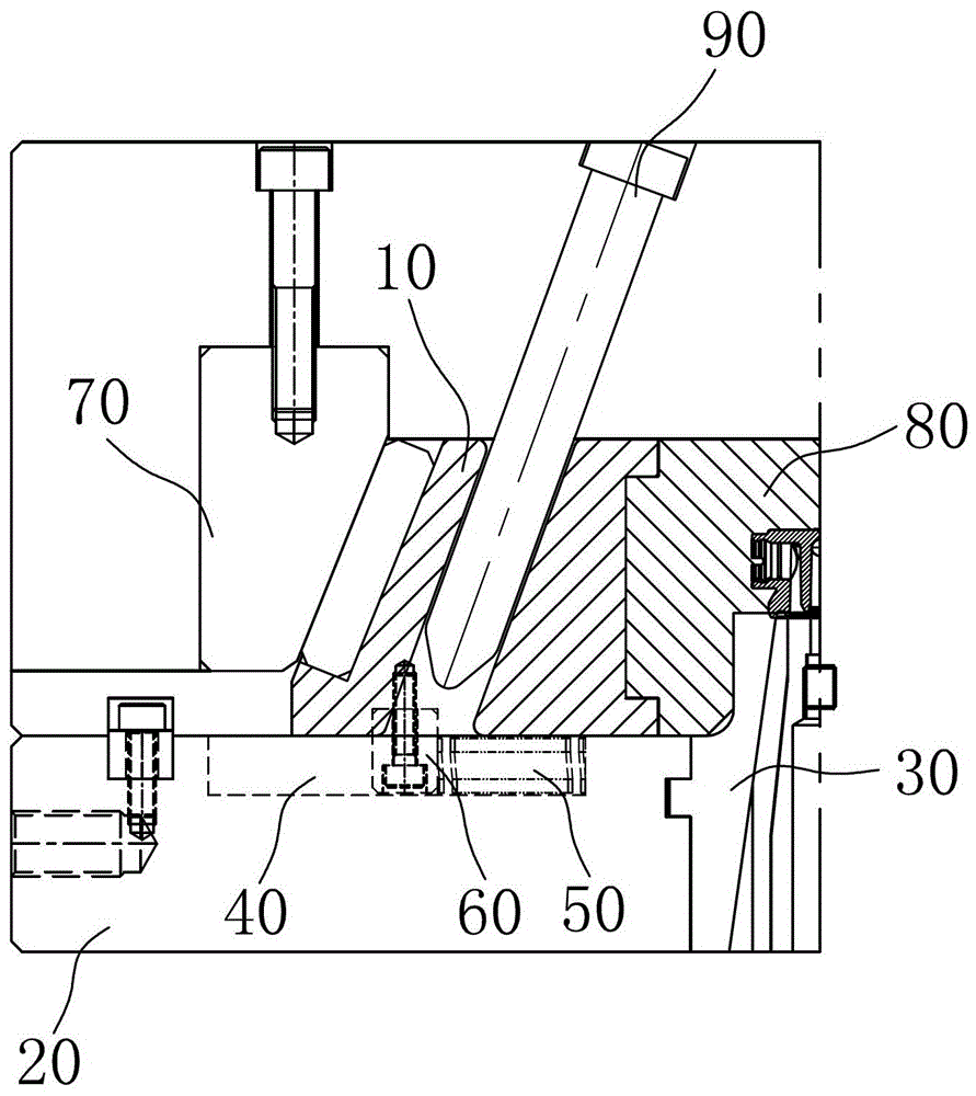
[0018] see figure 2 , figure 2 It is a structural schematic diagram of a mold clamping state of a preferred embodiment of the spring structure of the mold slider of the present invention.

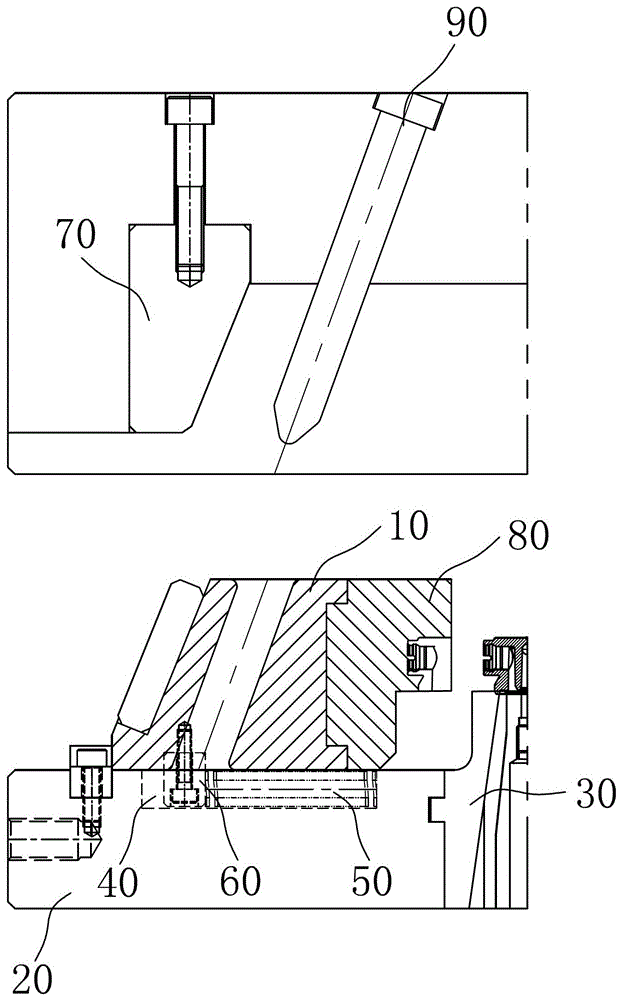
[0019] In order to achieve the above object, the spring structure of the mold slider provided by the present invention, the mold has a slider 10, a template 20 arranged below the slider 10, a mold core 30 arranged in the template 20, the spring Structures include:

[0020] A chute 40, which is arranged in the template 20, and the chute 40 opens toward one side of the slider 10;

[0021] A spring 50, which is arranged in the chute 40, and one end of the spring 50 is against the end of the chute 40 close to the mold core 30;

[0022] The stopper 60 is fixed on the bottom of the slider 10 , and one side of the stopper 60 bears against the end of the spring 50 away from the mold core 30 .

[0023] Wherein, the chute 40 is a U-shaped groove, which is convenient to be fabricated on the temp...


PUM


Abstract

The invention discloses a spring structure of a die slider, wherein a die is provided with the slider, a template arranged under the slider, and a die cavity formed in the template; and the spring structure comprises a sliding groove formed in the template, a spring arranged in the sliding groove and a stop block fixed at the bottom of the slider, the side of the sliding groove toward the slider is open; one end of the spring is propped against one end of the sliding groove in the vicinity of the die cavity; and one side of the stop block is propped against one end of the spring far away from the die cavity. The spring structure of the die slider provided by the invention is characterized in that the size of the slider does not need to be increased because the spring is arranged in the sliding groove of the template; therefore, the thickness of the die cavity and the template does not need to be increased, and the cost of the die is saved; the position of the sliding groove on the template is flexible and not limited, so that the mounting position of the spring is quite flexible; and as the spring is arranged on the bottom of the slider, interferences with an inclined guide column and a water route cannot be caused.

Description

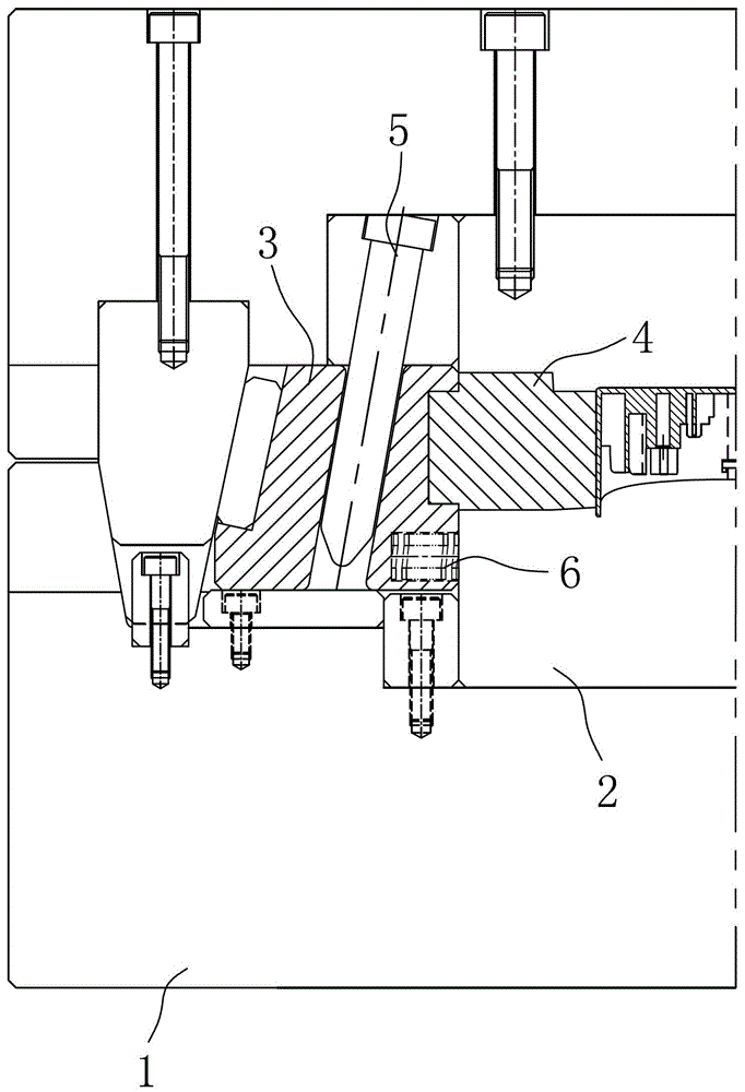
【Technical field】 [0001] The invention relates to a spring structure, in particular to a spring structure of a mold slider. 【Background technique】 [0002] When producing the housing of electronic products, plastic molds are usually used, and some molds need to use sliders when molding products. When molds using sliders are opened, in order to prevent the sliders from returning, usually Will be designed with a spring. [0003] see figure 1 , figure 1 It is a schematic diagram of the spring structure of the mold slider in the prior art. The mold has a template 1, a core 2, a slide block 3, a slide block insert 4, an inclined guide post 5, and a spring 6. The slider 3 has a hole near the mold core 2 , one end of the spring 6 is arranged in the hole of the slider 3 , and the other end is against the mold core 2 . [0004] However, adopting the above-mentioned structure has the following problems: 1. The slider 3 needs to be made large enough to accommodate the spring 6. In...

Claims


Application Information

Patent Timeline
Patent Type & Authority Patents(China)
IPC IPC(8): B29C33/20
Inventor 靳永晶
Owner MITAC PRECISION TECH(KUNSHAN) CORP
Learn More