Ejector mechanism of injection mould for automobile bumper

A technology for automobile bumpers and injection molds, applied in the field of auto parts, can solve problems such as affecting the normal production of products, easy to break the barrel, easy to pull and crack, etc.

Active Publication Date: 2014-05-07
CHONGQING CHANGAN AUTOMOBILE CO LTD
View PDF4 Cites 3 Cited by
  • Summary
  • Abstract
  • Description
  • Claims
  • Application Information

AI Technical Summary

Problems solved by technology

[0002] For the products with BOSS column structure on the bumper body of the automobile front bumper, three schemes are generally adopted in the design of the mold structure; 1. The BOSS column adopts the original flow or insert structure, and the BOSS column has no ejection when the product is demolded structure, the root of the BOSS column is easy to crack or break in the core when the mold is forced to be demoulded, the product is scrapped, and the mold needs to clean the broken glue position of the BOSS column, this failure will occur repeatedly, and mass production cannot be carried out; 2. The cylinder structure is ejected, because the thickness of the bumper mold is relatively large, but the thickness of the cylinder is about 2mm and the length is about 1000mm, which leads to a risk in the strength of the cylinder. When the boss column is ejected, the cylinder is easy to break and must be removed and replaced. 3. The BOSS column adopts the original flow or insert structure. In order to prevent the BOSS column from breaking when demoulding, the demoulding slope is increased during product design, and the glue position at the root of the BOSS column is also reduced. Correspondingly thickened, resulting in sink marks on the appearance of the product, and the product is scrapped

Method used


Image

  • Ejector mechanism of injection mould for automobile bumper
  • Ejector mechanism of injection mould for automobile bumper
  • Ejector mechanism of injection mould for automobile bumper

Examples


Embodiment Construction

[0014] The present invention will be further described below in conjunction with the accompanying drawings.

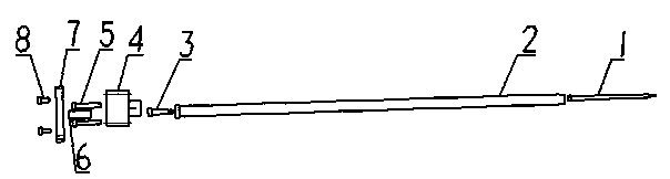
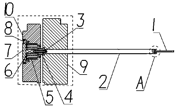
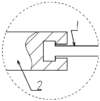
[0015] figure 1 It is a structural schematic diagram of a two-stage straight top according to the present invention, including a small straight top 1, a large straight top 2, a first screw 3, a fixing seat 4, a second screw 5, a spring 6, a cover plate 7, a third screw 8. Small straight jack 1 is contained in one end of big straight jack 2, and big straight jack 2 passes ejector plate 9, and the other end is positioned at ejector plate, and is limited by the limit step on ejector plate. The first screw 3 passes through the fixed seat 4 and is connected and fixed on the end of the large straight top 2 located in the thimble plate; the fixed seat 4 is connected and fixed on the movable mold bottom plate 10 by the second screw 5; the spring 6 is located in the fixed seat 4 One end of the spring 6 is in contact with the nut of the first screw 3, and the other end of the ...


PUM


Abstract

The invention provides an ejector mechanism for demoulding in the production of automobile front bumpers. The mechanism includes a large ejector, a small ejector, a fixed seat, a spring, a first screw, a second screw, a third screw, a cover plate, an ejector plate and a movable mold baseplate. The small ejector is mounted at one end of the large ejector, the large ejector passes through the ejector plate, and the other end is located in the ejector plate and is limited by a limiting step on the ejector plate; the first screw penetrates through the fixed seat and is fixedly connected with the end, located in the ejector plate, of the large ejector; the fixed seat is fixed on the movable mold baseplate by the second screw; the spring is located in the fixed seat, one end of the spring contacts with the nut of the first screw, and the other end of the spring is pressed by the cover plate; and the cover plate is fixedly connected to the movable mold baseplate by the third screw. The ejector mechanism provided by the invention can be pushed out by the spring force during demoulding to complete the demoulding of the product, and is simple for assembling and convenient for repair.

Description

technical field [0001] The invention relates to auto parts, in particular to an ejection structure of an injection mold for an auto bumper. Background technique [0002] For the products with BOSS column structure on the bumper body of the automobile front bumper, three schemes are generally adopted in the design of the mold structure; 1. The BOSS column adopts the original flow or insert structure, and the BOSS column has no ejection when the product is demolded structure, the root of the BOSS column is easy to crack or break in the core when the mold is forced to be demoulded, the product is scrapped, and the mold needs to clean the broken glue position of the BOSS column, this failure will occur repeatedly, and mass production cannot be carried out; 2. The cylinder structure is ejected, because the thickness of the bumper mold is relatively large, but the thickness of the cylinder is about 2mm and the length is about 1000mm, which leads to a risk in the strength of the cy...

Claims


Application Information

Patent Timeline
Patent Type & Authority Applications(China)
IPC IPC(8): B29C45/40B29L31/30
CPCB29C45/4005B29L2031/3044
Inventor 徐科王志白王晓
Owner CHONGQING CHANGAN AUTOMOBILE CO LTD
Why Eureka
Try Eureka