
Variable combined encryption lock

An encrypted lock and variable technology, applied in the direction of building locks, cylinder pin locks, locks with turning keys, etc., can solve the problems of user waste, waste of traditional integrated lock structure, safety, hidden dangers, etc., and achieve the effect of saving materials

Active Publication Date: 2014-05-07
YANTAI TRI CIRCLE SCI & TECH
View PDF5 Cites 3 Cited by
  • Summary
  • Abstract
  • Description
  • Claims
  • Application Information

AI Technical Summary

Problems solved by technology

Traditional one-piece locks, due to the integrated design of the lock body, lock cylinder, and pin, have corresponding keys. Generally, if the key is lost or the key is duplicated, for safety reasons, limit the unlocking authority or The person who steals and duplicates the mechanical key (knows the password or has the corresponding mechanical key) to open the lock must replace it with a new one. A lock that is intact will become a useless lock just because one person knows the password or the key is stolen. Users cause unnecessary waste
This kind of situation happens frequently in the occasions where the unlocking personnel change frequently, such as rented houses and hotels. There is a certain waste and safety hazard in the use of the traditional integrated lock structure.

Method used


Image

  • Variable combined encryption lock
  • Variable combined encryption lock
  • Variable combined encryption lock

Examples


Embodiment Construction

[0027] Hereinafter, with reference to the drawings, specific embodiments of the present invention are given to further illustrate the structure of the present invention. The embodiments of the present invention include but are not limited to the following examples.

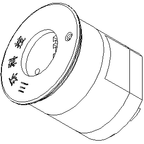
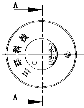
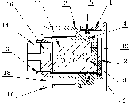
[0028] The variable combination encryption lock of this embodiment is characterized in that the lock body 3 is equipped with a first lock core 11 and a second lock core 19, as attached image 3 , 4 As shown, 6 pin springs 10 and 6 pin 9 are respectively installed in the two lock cylinders. The head end of the lock body is equipped with a lock cylinder end 6, and one end of the second lock cylinder 19 is connected with the lock cylinder end; The tail end of the body is equipped with a lock cylinder tail 16, one end of the first lock cylinder 11 is connected with the lock cylinder tail; the lock cylinder tail 16 is sleeved with a lock body back cover 17 and a copper sleeve 13, and the copper sleeve contact surface 13-1 ...


PUM


Abstract

The invention relates to a variable combined encryption lock, belonging to the technical field of encryption lockset structures. The variable combined encryption lock comprises a lock body and lock cylinders, and is characterized in that 2-6 lock cylinders are connected in series in the lock body; a marble spring and a marble are arranged in each lock cylinder respectively; the head end of the lock body is provided with a lock cylinder end, and one end of a first lock cylinder is connected with the lock cylinder end; the tail end of the lock body is provided with a lock cylinder tail, and one end of a tail end lock cylinder is connected with the lock cylinder tail; a lock body back cover and a copper sleeve are sleeved on the lock cylinder tail, and the contact surface of the copper sleeve is contacted with the contact surface of the lock body back cover; the lock cylinder tail is provided with a fixing groove, and a spring ring is buckled into the fixing groove on the lock cylinder tail to fix the relative positions of the copper sleeve, the lock body back cover and each lock cylinder in the lock body; the lock body back cover is fixed together with the lock body through a screw; a decorating sleeve is sleeved at the head end of the lock body; a drilling-resistant sheet is arranged in the decorating sleeve. A lock cylinder portion consists of the lock cylinder end, the lock cylinders and the lock cylinder tail, and the internal structure of the lock can be changed by replacing assemblies or changing the positions of the assemblies, thereby changing the internal structure of the lock and fulfilling the aim of replacing with a new lock. The variable combined encryption lock is convenient and practical.

Description

Technical field [0001] The invention relates to a variable combination encryption lock, belonging to the technical field of encryption lock structures. Background technique [0002] With the improvement of people’s living standards, people’s requirements for home safety are getting higher and higher, and the anti-theft door locks that are compatible with it are also constantly moving towards the goal of higher anti-theft; at the same time, there are many other important areas for locks. The anti-theft performance puts forward higher requirements. Traditional one-piece locks, due to the integrated design of the lock body, lock core, and pin structure, have a corresponding key. Generally, if the key is lost or the key is copied, for safety reasons, restrict the unlocking authority or The person who steals the copied mechanical key (knows the password or has the corresponding mechanical key) opens the lock, and must replace it with a new lock, an intact lock, just because one perso...

Claims


Application Information

Patent Timeline
Patent Type & Authority Applications(China)
IPC IPC(8): E05B27/00E05B15/14
Inventor 张永治陈乃忠杜媛丁希香
Owner YANTAI TRI CIRCLE SCI & TECH
Learn More