
Improved structure of diverting valve

An improved structure and diverter valve technology, applied in the valve shell structure, valve details, multi-way valve, etc., can solve the problems of time-consuming, laborious, manpower, suspension of machines and professional equipment, inconvenience, etc.

Inactive Publication Date: 2020-06-05
TAIWAN CONTROL VALVE
View PDF5 Cites 0 Cited by
  • Summary
  • Abstract
  • Description
  • Claims
  • Application Information

AI Technical Summary

Problems solved by technology

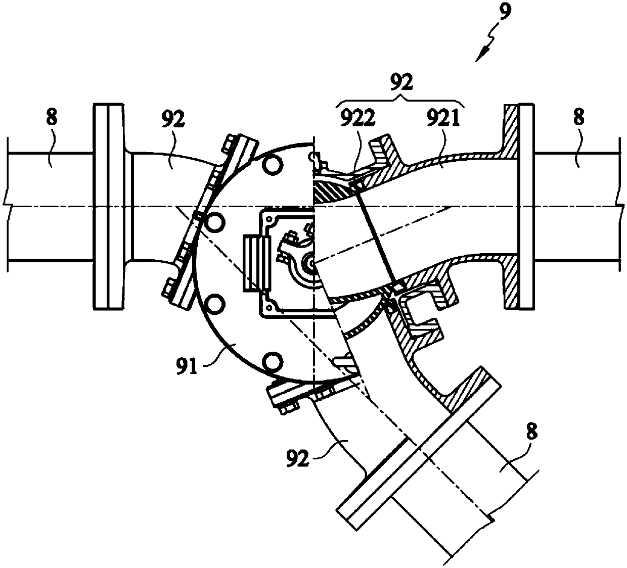
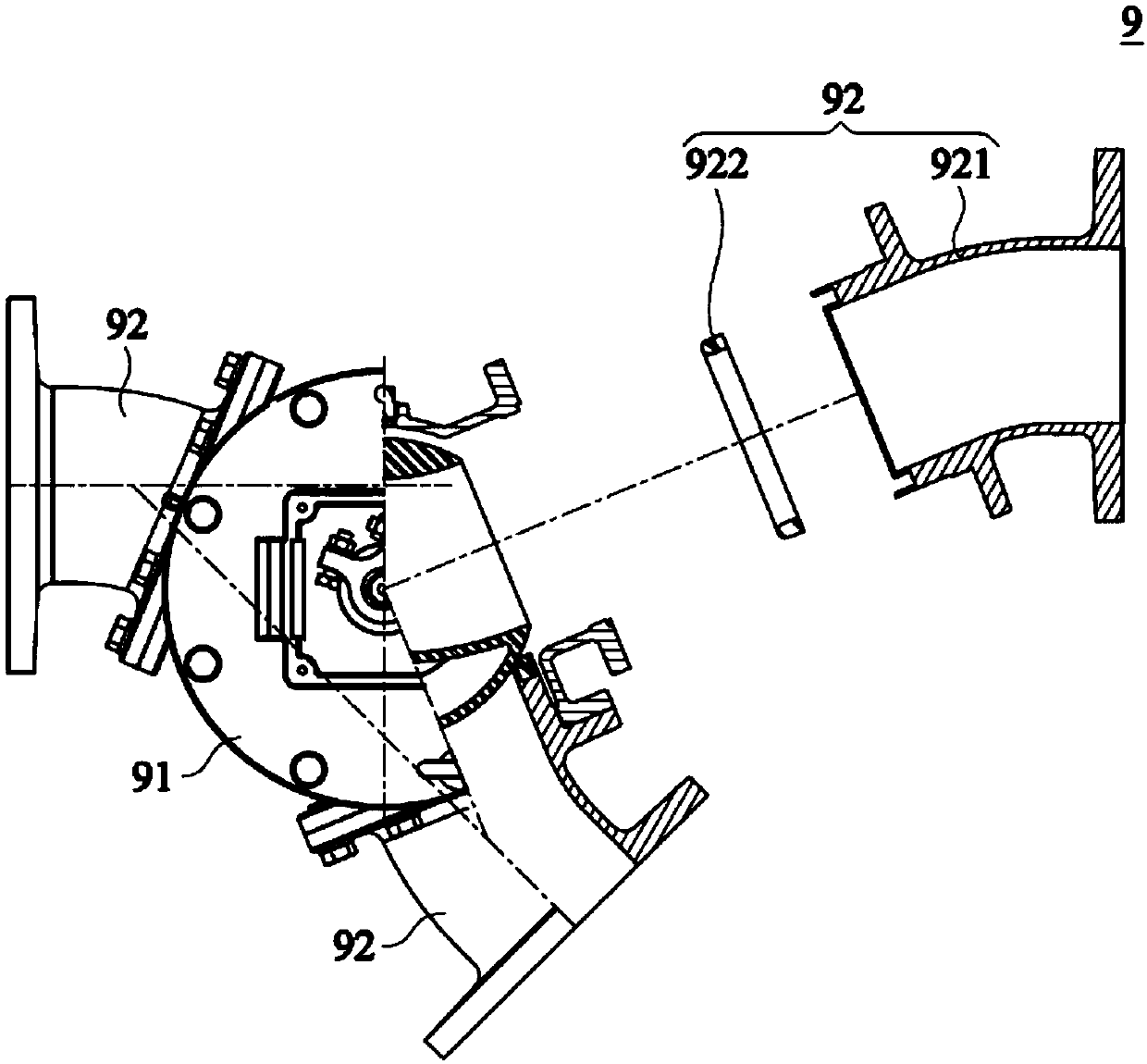
[0006] However, the above-mentioned existing valve seat 922 replacement operation requires more manpower, suspension machines and professional equipment to complete, which is time-consuming and laborious, and is extremely inconvenient

Method used


Image

  • Improved structure of diverting valve
  • Improved structure of diverting valve
  • Improved structure of diverting valve

Examples


Embodiment Construction

[0030] Please also refer to Figure 4 to Figure 6 ,in Figure 4 It is a top view of a preferred embodiment of the present invention, Figure 5 It is one of the disassembly schematic diagrams of a preferred embodiment of the present invention, Figure 6 It is the second disassembly schematic diagram of a preferred embodiment of the present invention.

[0031] Such as Figure 4 to Figure 6 As shown, the improved structure 1 of the directional valve of the preferred embodiment of the present invention includes a directional valve body 2 and a plurality of flow passages 3, wherein the number of flow passages 3 is three in this embodiment, and are respectively connected to the group Set to the diverter valve body 2, as detailed below.

[0032] Figure 4 to Figure 6 The diverter valve body 2 shown includes an inner chamber 21 and a plurality of passages 22, the number of the plurality of passages 22 corresponds to the plurality of flow passages 3, that is, three, and the plural...


PUM


Abstract

The invention discloses an improved structure of a diverting valve. The improved structure comprises a diverting valve body and multiple flow channels; the diverting valve body comprises an accommodating chamber and multiple channels; the multiple channels communicate with the accommodating chamber; the number of the multiple flow channels corresponds to the number of the multiple channels; each flow channel comprises a connecting part, a valve seat ring and a valve seat, the valve seat is arranged in the corresponding channel and is next to the diverting valve body, the valve seat ring is arranged on the valve seat, and the corresponding flow channel is connected to the channel through the connecting part. Thus, the purpose of improving the convenience of mounting and dismounting operations can be achieved really.

Description

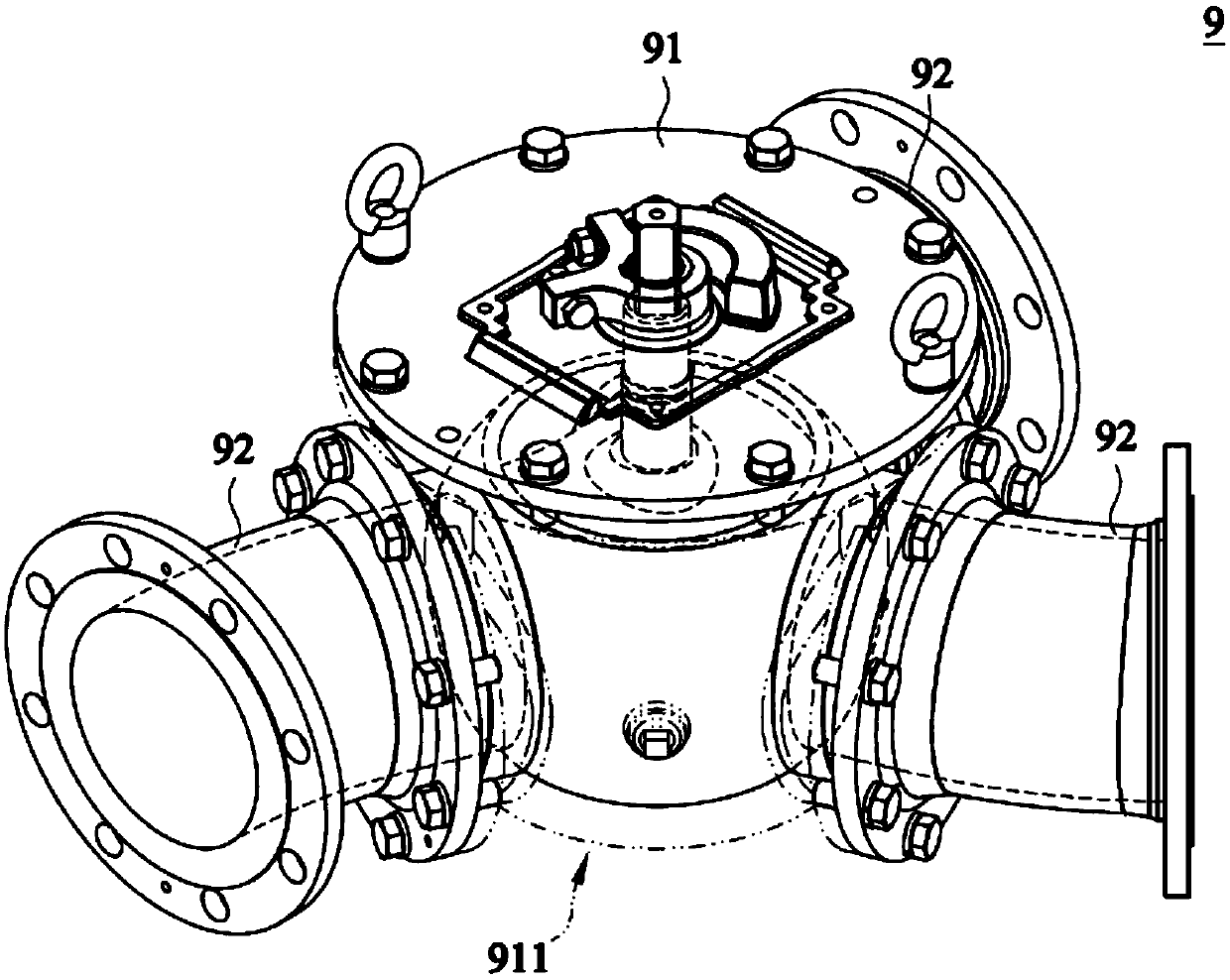
technical field [0001] The invention relates to an improved structure of a directional valve, especially an improved structure of a directional valve that can surely achieve the purpose of improving the convenience of disassembly and assembly. Background technique [0002] In mechanical equipment, fluids such as gas or liquid are usually transported through pipelines, and in order to transport fluids to pipelines in different directions, diverter valves are installed in the pipelines to switch the flow direction. [0003] Please also refer to Figure 1 to Figure 3 ,one of them figure 1 is a perspective view of an existing diverter valve, figure 2 is the top view of the existing diverter valve, image 3 It is a schematic diagram of the disassembly of the existing diverter valve. [0004] Such as Figure 1 to Figure 3 As shown, the existing diverter valve 9 has a diverter valve body 91 and a plurality of flow passages 92, each flow passage 92 is installed to the diverter ...

Claims


Application Information

Patent Timeline
Patent Type & Authority Applications(China)
IPC IPC(8): F16K11/087F16K27/06
CPCF16K11/087F16K27/067
Inventor 施丽月叶礼祯
Owner TAIWAN CONTROL VALVE
Learn More