Drilling power rock debris bed eraser

A power-while-drilling and cuttings bed technology, which is applied in earthwork drilling, wellbore/well components, flushing wellbore, etc., can solve the problems of affecting drilling efficiency, collapsing blocks in soft strata, and high cost

Active Publication Date: 2014-05-07
CHINA PETROLEUM & CHEM CORP +1
View PDF5 Cites 17 Cited by
  • Summary
  • Abstract
  • Description
  • Claims
  • Application Information

AI Technical Summary

Problems solved by technology

[0004] Aiming at the problems that the speed-returning method is easy to cause soft formations to collapse and blocks, the method of improving mud performance is high in cost, and the mechanical removal method is short and affects the drilling efficiency. Drilling and other construction sites provide powered cuttings bed removers while drilling

Method used


Image

  • Drilling power rock debris bed eraser
  • Drilling power rock debris bed eraser

Examples


Embodiment Construction

[0015] The present invention will be described in detail below in conjunction with the accompanying drawings.

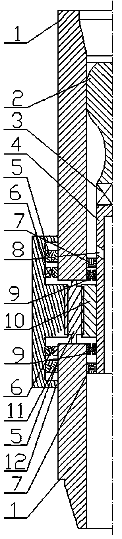
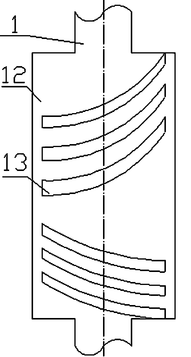
[0016] Such as figure 1 , the screw 2, the cardan shaft 3 and the central shaft 4 are installed inside the housing 1, the sealing device 7 and the bearing 9 are installed between the central shaft 4 and the inner wall of the housing 1, the bypass hole 8 is processed on the central shaft 4, and the central shaft 4 The interior is a hollow structure, the driving gear 10 is installed on the central shaft 4, and the three planetary gears 11 are installed in the housing 1, and are evenly distributed at 120 degrees. The driving gear 10 meshes with the three planetary gears 11 at the same time, and the cutting sliding sleeve 12 Installed outside the casing 1, the sealing device 5 and the bearing 6 are installed between the cutting sliding sleeve 12 and the outer wall of the casing 1, and the inner wall of the cutting sliding sleeve 12 is processed with a ring gear and meshe...


PUM


Abstract

A drilling power rock debris bed eraser comprises a casing, a screw, a cardan shaft, a center shaft, a sealing device, a bearing, a by-pass hole, a driving gear, planet gears and a cutting sliding sleeve. The screw, the cardan shaft and the center shaft are installed in the casing after being connected sequentially, the center shaft is internally of a hollow structure, the by-pass hole is processed in the center shaft, the driving gear is installed on the center shaft, more than two planet gears are arranged in the circumferential direction of the casing corresponding to the driving gear, the outer portion of the casing corresponding to the planet gears is sleeved with the cutting sliding sleeve, and a cutting ridge is processed and installed on the outer portion of the cutting sliding sleeve. The driving gear, the planet gears and a protruded gear ring on an inner wall of the cutting sliding sleeve are sequentially in meshed connection. The eraser can rotatably scrape a rock debris bed when drilling fluid passes or the eraser is in a rotary drilling state or a sliding drilling state; and the drilling power rock debris bed eraser can transmit bit pressure and torque and drive a shaft bottom drill bit to break rock. The drilling power rock debris bed eraser has the advantages of being simple and reliable in structure design, convenient to process and high in transmitting torque and running stably.

Description

technical field [0001] The invention belongs to a power cuttings bed remover while drilling and mainly relates to the fields of oil and gas drilling, coal bed gas drilling, geological exploration, mine drilling and the like. Background technique [0002] During the drilling process, the formation of cuttings bed will cause many drilling problems. ①Increase the solid phase content of annular mud, reduce the annular gap, form an elliptical borehole, and cause the pump to hold; ②It is easy to form keyways and steps, causing downhole accidents; ③During drilling, the suspension weight and WOB are distorted; ④The torque of the centralizer and drill collar increases or the mud bag of the centralizer causes the drilling to be held back. In addition, the sinking of cuttings causes sand sticking or sticking, which affects drilling safety. [0003] At present, the methods for removing cuttings beds mainly include: ① Increase the return velocity method. The higher the return velocity i...

Claims


Application Information

Patent Timeline
IPC IPC(8): E21B21/00
Inventor 李文飞周延军夏文安耿应春李玄烨于丽丽于丽萍
Owner CHINA PETROLEUM & CHEM CORP
Why Eureka
Try Eureka