Cylinder lubrication system

A lubrication system and cylinder technology, applied in the direction of timing lubrication, pressure lubricant, lubrication parts, etc., can solve the problem of not necessarily eliminating the lubrication of the upper cylinder

Inactive Publication Date: 2014-05-07
GM GLOBAL TECH OPERATIONS LLC
View PDF6 Cites 3 Cited by
  • Summary
  • Abstract
  • Description
  • Claims
  • Application Information

AI Technical Summary

Problems solved by technology

While this application addresses the emissions challenges of 2-stroke desig...

Method used


Image

  • Cylinder lubrication system
  • Cylinder lubrication system

Examples


Embodiment Construction

[0037] The following description is merely exemplary in nature, and is not intended to limit the disclosure, its application, or uses. It should be understood that throughout the drawings, corresponding reference numerals indicate like or corresponding parts or features. As used herein, the term module or control module refers to an application-specific integrated circuit (ASIC), an electronic circuit, a processor (shared, dedicated, or grouped), and memory that executes one or more software or firmware programs, Combinational logic circuits and / or other suitable means of providing the desired functionality.

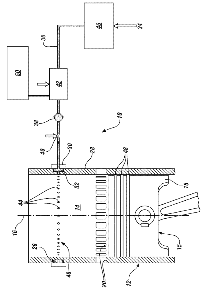
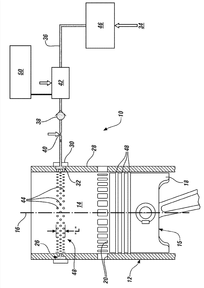
[0038] now refer to figure 1 , an exemplary embodiment involves a piston reciprocating within a cylinder (and in this exemplary embodiment, part of internal combustion engine 10 ). In this example, the internal combustion engine is a 2-stroke engine comprising a cylinder liner 12 containing a cylinder 14 having a piston 15 reciprocally mounted therein for axial travel ...


PUM

PropertyMeasurementUnit
Diameteraaaaaaaaaa

Abstract

The invention relates to a cylinder lubrication system, comprising a cylinder liner defining a cylinder, a piston reciprocally mounted in the cylinder for axial travel along a cylinder axis and having a piston skirt that moves in close proximity with the cylinder, an oil supply passage extending substantially circumferentially about an outer surface of the cylinder liner, an oil supply line fluidly connecting the oil supply passage to an oil supply, a series of small holes extending radially through the cylinder liner, from the cylinder to the oil supply passage, and operable as oil passages for lubricating oil from the oil supply to flow to the upper portion of the cylinder.

Description

technical field [0001] Exemplary embodiments of the present invention relate to engine cylinder lubrication systems, and more particularly, to the lubrication of cylinders with low upper cylinder lubrication (not readily lubricated by crankcase oil). Background technique [0002] Internal combustion engines typically require adequate lubrication between all moving parts to ensure efficient operation and long life. This is especially true between the cylinder wall and the cylinder. In certain engine types, such as 2-stroke engines and other engines that do not rely on oil supplied from the crankcase for cylinder / wall lubrication, it is necessary to provide alternative lubrication. Historically, 2-stroke engines have used a mixture of fuel, oil and air as the combustion charge in order to provide this lubrication. However, with increasing concerns about emissions from internal combustion engines, the addition of oil as a combustion component of the combustion feed has in som...

Claims


Application Information

Patent Timeline
IPC IPC(8): F02F1/20F01M1/16
CPCF01M1/16F02F1/20F01M1/08F01M1/14F01M11/02F01M2001/083F01M2011/022
Inventor R.D.斯特劳布
Owner GM GLOBAL TECH OPERATIONS LLC
Why Eureka
Try Eureka