This helps you quickly interpret patents by identifying the three key elements:
Problems solved by technology
Method used
Benefits of technology
Problems solved by technology
[0003] However, the existing claw rotors have a common defect that needs to be improved, that is, noise and vibration will be generated during the mutual meshing process. The reason is that the two claws of the claw rotor form a discontinuity at the tip curve. The compression movement process of the cycle defines that the rotor and the conjugate rotor have an unsmooth curve at the tip, which makes the two claws mesh poorly, which will generate noise and vibration during the compression movement process, or even cause friction due to improper engagement. and mechanism fatigue, which reduces service life
Method used
Image
Click on the blue label to locate the original text in one second.
Reading with bidirectional positioning of images and text.
Examples
Embodiment Construction
[0034] In order to further illustrate the technical means adopted by the present invention and its effects, the following describes in detail the preferred embodiments of the present invention and the accompanying drawings.
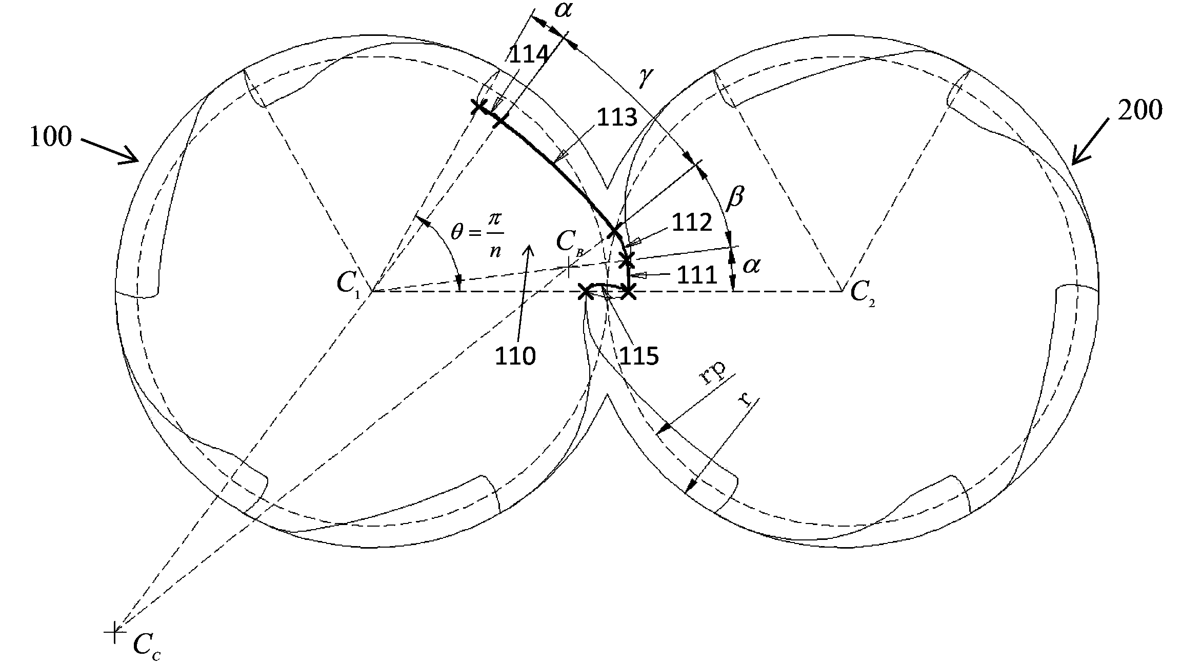
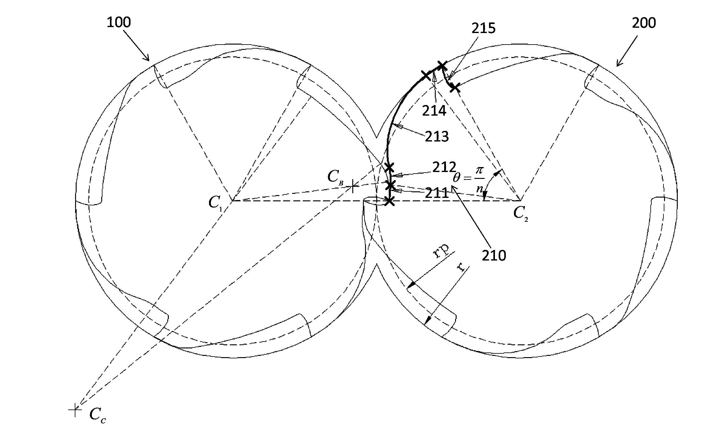
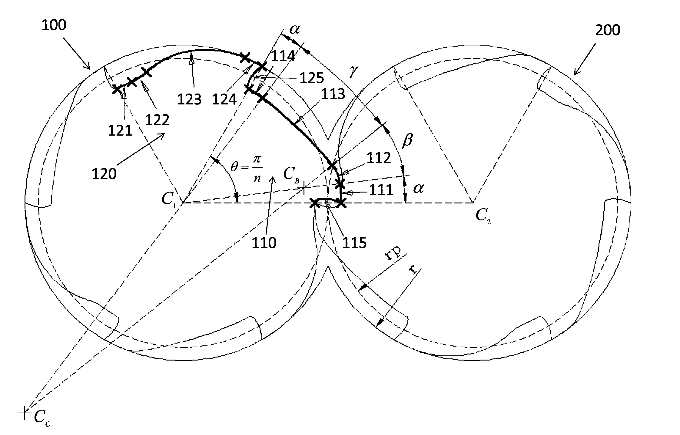
[0035] See Figure 1 to Figure 4 , The two claw-type rotor pair devices with the same shape of the present invention are composed of a defined rotor 100 and a conjugate rotor 200 that mesh with each other, such as figure 1 As shown, in the first embodiment, the definition of the rotor 100 and the conjugate rotor 200 with the same configuration of 6 claws is used as an introduction. The cross-sectional profile 110 of the first claw portion of the defined rotor 100 is obtained by a nonlinear equation, that is, the Define the tip and root contours of the single claw of the rotor 100, and then obtain the tip and root contours of the single claw of the conjugate rotor 200 by the conjugate theory (ie. figure 2 As shown, the cross-sectional profile 210 of the first...
PUM
Abstract
The present invention provides a claw type rotor pair apparatus with two rotors having the same shape, wherein the claw type rotor pair apparatus comprise a defined rotor and a conjugate rotor, the defined rotor and the conjugate rotor are mutually engaged, the structure shapes of the mutually-engaged rotors are the same, the cross-sectional shape of the first claw portion of the defined rotor sequentially comprises five curves such as an epicycloid, a first arc, a second arc, a third arc and a fourth arc in the anticlockwise direction, the intersection points of the four sections of the arcs meet the limitation condition of slope continuity, the circle center positions, the radiuses and the arc angle values of the second arc and the third arc can be suitably selected according to the limitation condition and the geometry relationship, the cross-sectional shape of the first claw portion of the conjugate rotor can be obtained through a conjugate curve calculation manner in the clockwise manner, and other claw portions of the defined rotor and the conjugate rotor can be respectively obtained through staggered copy rotation.
Description
Technical field [0001] The invention relates to a claw-type rotor pairing device, in particular to a pair of mutually meshing rotors, which have the same configuration, can make the mutual conjugate meshing process smoothly, will not produce noise and mechanism fatigue, and can provide an even number of meshing claws with parameters Number of two claw-type rotor pair devices with the same shape. Background technique [0002] Existing claw-type rotors are based on different actual needs. The claws on the two rotors have odd-numbered or even-numbered claws. However, no matter which type is used, the structure of the claw-type rotor basically includes: two mutual The definition of conjugate meshing is the rotor and the conjugated rotor. The claws on the two rotors perform conjugated meshing rotation to provide a cyclic compression movement. For the structure of the related claw rotor, please refer to US Patent No. 1,426,820, No. 5,149,256, 4,406,601, 4,324,538, 4,224,016 and 4,430,...
Claims
Application Information
Patent Timeline
Application Date:The date an application was filed.
Publication Date:The date a patent or application was officially published.
First Publication Date:The earliest publication date of a patent with the same application number.
Issue Date:Publication date of the patent grant document.
PCT Entry Date:The Entry date of PCT National Phase.
Estimated Expiry Date:The statutory expiry date of a patent right according to the Patent Law, and it is the longest term of protection that the patent right can achieve without the termination of the patent right due to other reasons(Term extension factor has been taken into account ).
Invalid Date:Actual expiry date is based on effective date or publication date of legal transaction data of invalid patent.

