Wear resistant vapor deposited coating, method of coating deposition and applications therefor

a technology of vapor deposited coating and wear resistance, which is applied in the direction of solid-state diffusion coating, natural mineral layered products, and teeth capping, etc., can solve the problems of requiring a low surface roughness of deposited layers, and reducing the wear resistance and durability of surgical instruments and dental tools. , to achieve the effect of reducing the stickiness and friction of rotary instruments, reducing to

Active Publication Date: 2007-12-13
G&H TECH LLC
View PDF21 Cites 140 Cited by
  • Summary
  • Abstract
  • Description
  • Claims
  • Application Information

AI Technical Summary

Benefits of technology

[0013] An object of invention is to obtain a stable cutting edge consisting of multilayer coating with different architectures on both sides of the blade of a rotary tool. These coatings primarily focus on reduction of stickiness and friction of the rotary instruments to reduce torsion fatigue when they come in contact with their counterpart. Other properties of the surface engineered instruments are dedicated for improvement of coating toughness, abrasion wear resistance and corrosion resistance.

Problems solved by technology

The vapour deposition of Schroeder is conducted at relatively low temperature, thus the substrate will have lost little of its initial high strength properties, however, the requirement of low surface roughness of the deposited layer is not addressed by U.S. Pat. No. 5,152,774.
Any post-deposition heat treatment which may be required to maintain maximum hardness of the substrate's core metal, may lead to internal stresses in the coating due to differences in the grain size, and can eventually lead to abrasion, spalling, crack formation, grain separation, surface fractures, uneven edges and rough surfaces, and the like, which can drastically reduce the wear resistance and durability of surgical instruments and dental tools.
The disadvantage of this approach is that more intensive wear on one side of the edge leaves the hard layer unsupported which eventually results in a failure of the more brittle hard layer by fracturing.
The soft side of the cutting edge has a higher wear rate which affects the support of the brittle thin film coating on the opposite side.
However, in operation the material on the softer side of the blade suffers greater wear and is not be able to support the harder coating on the opposite side of the blade.
Further, this method as well as the methods described previously, does not address issues of friction and galling properties of the coated surface on the cutting tool.
There are known methods described, wherein the cutting tips of surgical instruments made of steel have been sand-blasted and then coated with a hard-wearing ceramic composition, however this method can, and is likely to, increase surface roughness and unevenness, rather than eliminate it.
The main disadvantage of these methods is that the hard or even superhard coating with micro-hardness in excess of 20 GPa is deposited on relatively soft substrate surface made of steel or other alloy having micro-hardness less than 8 GPa.
This technology however is limited to selective types of steels and metal alloys due to poor adhesion of the hard coatings to most ionitrided metallic materials.

Method used


Image

  • Wear resistant vapor deposited coating, method of coating deposition and applications therefor
  • Wear resistant vapor deposited coating, method of coating deposition and applications therefor
  • Wear resistant vapor deposited coating, method of coating deposition and applications therefor

Examples


example 1

Stainless Steel Endofiles with Multilayer Gradient TiCr / TiCrN+TiCrCN+TiBC Coating

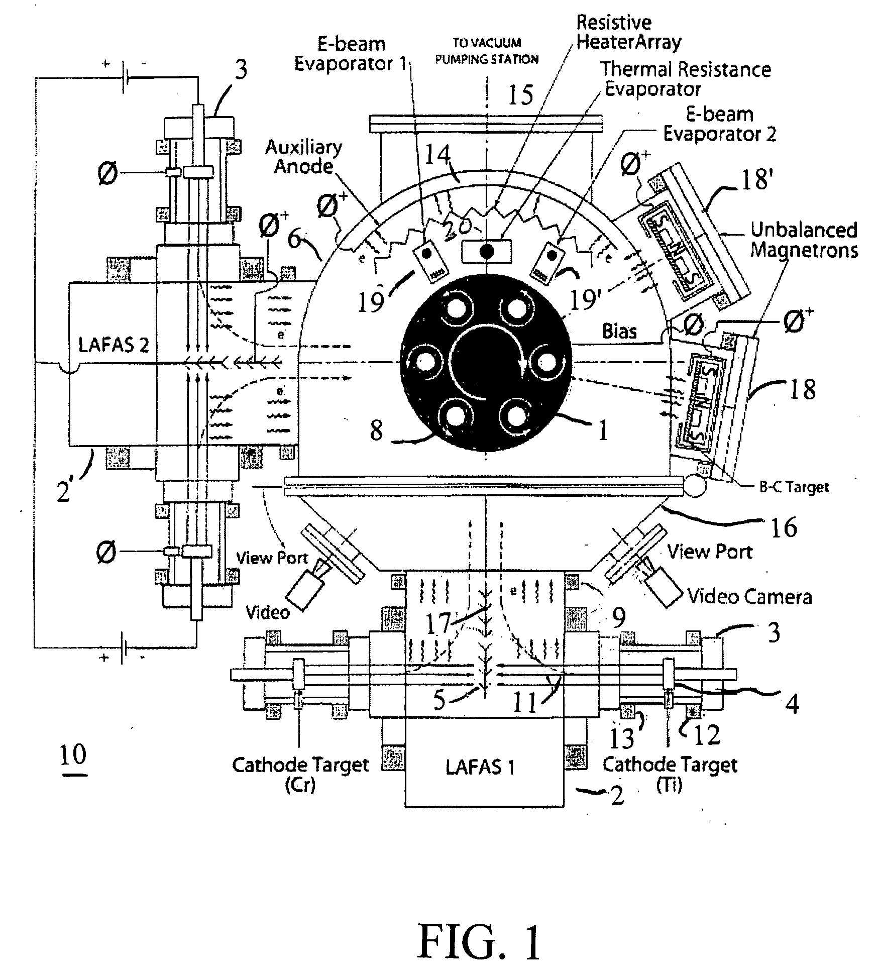
[0094] A set of endofiles made of 17-4 stainless steel were installed into the substrate holders positioned on the satellites of the rotating table of surface engineering system shown in FIG. 1. The following process parameters were used for the deposition of TiCrN / TiCr—TiCrCN bottom segment and transitional layer by LAFAD plasma source equipped with two (opposite) Ti and Cr targets. The arc currents were set on approximately 100 amperes for both Ti and Cr targets. The auxiliary arc discharge current was set on 150 amperes during argon ion cleaning stage and then reduced to 40 amperes during coating deposition stage. The substrate temperature did not exceed 300° C. An Advanced Energy Industry MDX-II power supply coupled with a Sparkle-V accessory unit was used as a bias power supply. The bias voltage was set at 250 volts during an ion cleaning stage followed by 1000 volts during 2 mins of a metal ion e...

example 2

NiTi Endofiles with Anti-Friction Carbon Diamond-Like Coating

[0095] A set of endofiles made of NiTi nickel-titanium alloy were placed in the copper blocks and installed in the substrate holders, positioned on the satellites of the rotating table of surface engineering system shown in FIG. 1. The thermal transfer or “thermal sink” compound (“Thermal Compound” Part # 120-8, manufactured by Wakefield Engineering Inc. of MA) was placed in the hole to reduce the thermal contact resistance between the instrument and the copper block so that instruments can be provided with substantial thermal conduction cooling during vapour plasma deposition process.

[0096] The following process parameters were used for the deposition of DLC low friction carbon coating using two LAFAD plasma sources, one (for bondcoating layer) equipped with two Ti targets and another one equipped with two graphite targets. The ion cleaning step was performed in argon ionized in auxiliary arc discharge, created between ...

example 3

Endodontic Files Made of 17-4 Stainless Steel with Two Segment Cermet-DLC Coating

[0098] A set of blank endofiles made of 17-4 stainless steel is cleaned by vibratory tumbling followed by ultrasonic cleaning dried and then loaded in the surface engineering system shown in FIG. 1. The surface finish of the blank endofile after cleaning is better than Rms—>25 GPa. This step forms a cutting flute with a metallic underside and a ceramic metal outer layer or top side. After that the instruments are subjected to chemical-mechanical vibratory tumbling which creates a fine surface finish on the uncoated side of the flute and does not affect the outer side of the flute and the very tip of the cutting edge which are much harder than vibratory tumbling media. After that the substrate instruments are ultrasonically cleaned and placed in the copper blocks positioned on the satellites of the rotating table of surface engineering system shown in FIG. 1. The thermal transfer or “thermal sink” compo...


PUM

PropertyMeasurementUnit
friction coefficientaaaaaaaaaa
thicknessaaaaaaaaaa
thicknessaaaaaaaaaa

Abstract

A low friction top coat over a multilayer metal/ceramic bondcoat provides a conductive substrate, such as a rotary tool, with wear resistance and corrosion resistance. The top coat further provides low friction and anti-stickiness as well as high compressive stress. The high compressive stress provided by the top coat protects against degradation of the tool due to abrasion and torsional and cyclic fatigue. Substrate temperature is strictly controlled during the coating process to preserve the bulk properties of the substrate and the coating. The described coating process is particularly useful when applied to shape memory alloys.

Description

CROSS-REFERENCE TO RELATED APPLICATIONS [0001] This application claims the benefits of U.S. Provisional Application No. 60 / 801,142, filed May 17, 2006, the disclosure of which is hereby incorporated by reference in its entirety including all figures, tables and drawings.FIELD OF INVENTION [0002] This invention relates to hard, wear resistant coatings vapour deposited over a metallic or non-metallic surface, in particular, the invention relates to a coating to be deposited on rotary tools having cutting edges utilized in industrial, medical and dental cutting, and form scraping, and is more particularly directed to improvements in blades and rotary cutting instruments. BACKGROUND OF THE INVENTION [0003] Hard wearing surfaces are in common use in various industries, and such hard wearing surfaces are frequently obtained by coating the surface of a tool made of steel or similar metal, or other hard, enduring material, with a layer of hard wearing ceramic substance, such as carbides, ni...

Claims


Application Information

Patent Timeline
Patent Type & Authority Applications(United States)
IPC IPC(8): C25D5/00C09D1/00
CPCA61B17/1615A61B2017/1602A61C3/02A61C5/023C23C14/024C23C14/025Y10T428/30C23C16/0272C23C16/0281Y10T428/24975Y10T428/252Y10T428/265C23C14/0605A61C5/42C21D6/004C21D6/005C21D6/008C22C14/00C22C19/03C22C38/001C22C38/002C22C38/02C22C38/04C22C38/06C22C38/20C22C38/22C22C38/42C22C38/44C22C38/50C22F1/10C22F1/183A61C1/00C23C14/02C23C14/06C23C16/02C23C28/00C23C8/02C23C8/20C23C8/24C23C8/36C23C14/021C23C14/022C23C14/0611C23C14/0635C23C14/0641C23C14/067C23C14/0676C23C14/0682C23C14/14C23C14/5806C23C14/586C23C14/588C23C16/0227C23C16/0236C23C16/06C23C16/24C23C16/26C23C16/28C23C16/32C23C16/34C23C16/38C23C16/42C23C16/56
Inventor GOROKHOVSKY, VLADIMIRHECKERMAN, BRAD B.
Owner G&H TECH LLC
Why Eureka
Try Eureka