Photoelectric sensor

A technology of photoelectric sensor and light receiving part, applied in the field of photoelectric sensor

Active Publication Date: 2014-05-07
ORMON CORP
View PDF5 Cites 3 Cited by
  • Summary
  • Abstract
  • Description
  • Claims
  • Application Information

AI Technical Summary

Problems solved by technology

[0006] However, it is not only the response time that is set in the photoelectric sensor

Method used


Image

  • Photoelectric sensor
  • Photoelectric sensor
  • Photoelectric sensor

Examples


Embodiment Construction

[0033] Hereinafter, embodiments of the photoelectric sensor will be described with reference to the drawings. In addition, the same reference numerals are attached to the same components in each figure, and detailed descriptions will not be repeated.

[0034] [Appearance of photoelectric sensor]

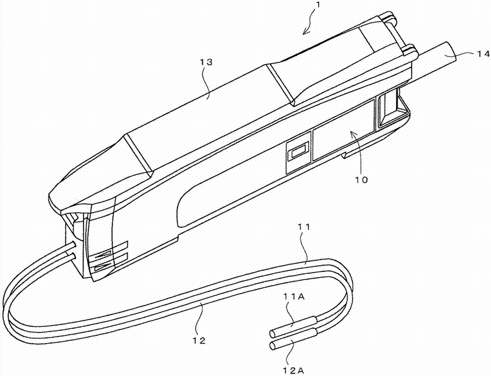
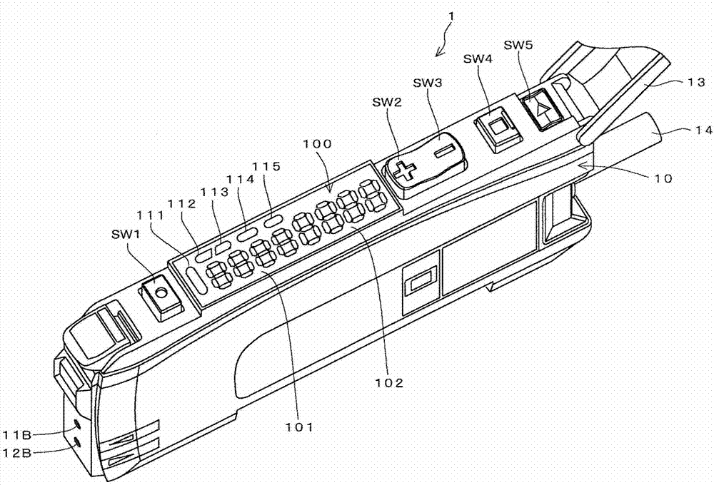
[0035] figure 1 and figure 2 It is a figure which shows the appearance of the fiber-optic photoelectric sensor which is one embodiment of a photoelectric sensor.

[0036] The photoelectric sensor 1 includes a main body 10 and a pair of optical fibers 11 and 12 attached to the front surface of the main body 10 . The optical fiber 11 is used for projecting light, and the other optical fiber 12 is used for receiving light. Heads 11A, 12A including lenses and the like are attached to the distal ends of the respective optical fibers 11, 12, respectively. In addition, the actual optical fibers 11 and 12 may be longer than those shown in the drawings.

[0037] The optical fibers 11 a...


PUM


Abstract

The invention provides a photoelectric sensor that provides useful information to set measurement conditions. The photoelectric sensor includes a light emitting unit having a light emitting element configured to emit detection light toward a detection area, a light receiving unit having a light receiving element configured to receive the detection light from the detection area and to obtain a detection value corresponding to the amount of light received, and a display device configured to display information representing the detection value in the light receiving unit. When the detection value varies across a predetermined threshold, the display device displays a transit time that is the time from when the detection value crosses the predetermined threshold until when it crosses the predetermined threshold again, and a variation amount of the detection value in the variation.

Description

technical field [0001] The present invention relates to a photoelectric sensor, in particular to a photoelectric sensor provided with a display unit. Background technique [0002] Photoelectric sensors are widely used to detect the presence or absence of moving objects in factory production lines and the like. Various techniques have conventionally been proposed for such a photoelectric sensor. [0003] For example, Patent Document 1 (Japanese Unexamined Patent Publication No. 2007-93464) discloses a technology that compares the amount of light received by the light receiving element of a photosensor with a threshold value, outputs an ON signal or an OFF signal, and displays a Information for judging the time for which an ON signal has been continuously output (ON time width) and the time for which an OFF signal has been continuously output (OFF time width). [0004] Patent Document 1: JP Unexamined Publication No. 2007-93464 [0005] Displaying the aforementioned on (ON)...

Claims


Application Information

Patent Timeline
IPC IPC(8): G01V8/10G01S17/04
CPCG01B11/00G01J1/18G01V8/10G01S7/4816G01S7/493G01S7/51G01S17/04
Inventor 大前壮司权藤清彦饭田雄介
Owner ORMON CORP
Why Eureka
Try Eureka