
Accident inversion system and accident inversion method of electric power dispatching automation system

An automation system and accident inversion technology, applied in instruments, data processing applications, resources, etc., can solve problems such as limited capture and accurate judgment, inability to save historical messages, and inability to support the inversion of power grid operating status at any time

Active Publication Date: 2014-05-07
NARI TECH CO LTD
View PDF4 Cites 6 Cited by
  • Summary
  • Abstract
  • Description
  • Claims
  • Application Information

AI Technical Summary

Problems solved by technology

[0002] At present, the accident inversion function provided by the domestic power dispatching automation system is based on the trigger history message storage mechanism when the accident occurs, that is, only when the defined event (such as: accident opening, accident jump, etc.) occurs The accident inversion and storage can only be triggered under the condition of the system. Therefore, this accident inversion mechanism is limited by the system’s capture and accurate judgment of the accident itself. When the accident itself is not accurately captured, it will not be able to perform inversion analysis.
Therefore, the existing accident inversion mechanism cannot support the inversion of the power grid operation status at any time. The main reason is that due to limited storage capacity and other reasons, it is impossible to save all the massive historical messages in the historical database.

Method used

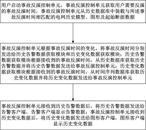

Image

  • Accident inversion system and accident inversion method of electric power dispatching automation system
  • Accident inversion system and accident inversion method of electric power dispatching automation system

Examples


Embodiment Construction

[0023] The present invention will be specifically introduced below in conjunction with the accompanying drawings and specific embodiments.

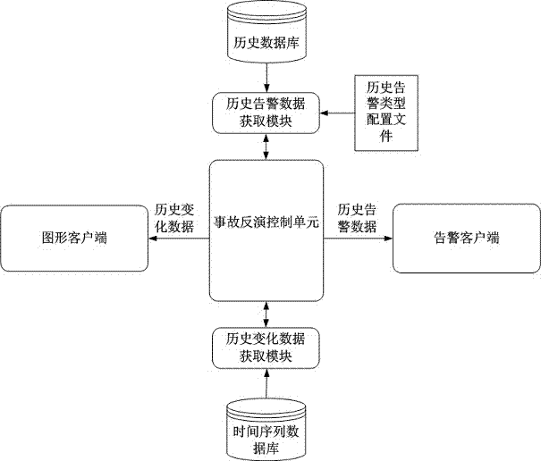
[0024] refer to figure 1 As shown, the accident inversion system of the power dispatching automation system of the present invention includes: an accident inversion control unit, a historical alarm data acquisition module, a historical database, a historical change data acquisition module, a time series database, a graphic client, and an alarm client; The inversion control unit is respectively connected to the historical alarm data acquisition module, the historical change data acquisition module, the graphic client display module, and the alarm client display module; the historical alarm data acquisition module is connected to the historical database; the historical change data acquisition module is connected to the time series database.

[0025] In the present invention, the historical database is used to store historical data, and the ...


PUM


Abstract

The invention discloses an accident inversion system and an accident inversion method of an electric power dispatching automation system. The accident inversion system of the electric power dispatching automation system is characterized by comprising an accident inversion control unit, a historical alarm data acquisition module, a historical database, a historical change data acquisition module, a time series database, a graphical client and an alarm client, wherein the accident inversion control unit is connected with the historical alarm data acquisition module, the historical change data acquisition module, a graphical client display module and an alarm client display module; the historical alarm data acquisition module is connected with the historical database; and the historical change data acquisition module is connected with the time series database. The invention further discloses an accident inversion method of the electric power dispatching automation system. The accident inversion system and the accident inversion method of the electric power dispatching automation system enables the dispatching monitoring personnel to carry out inversion on power grid data at any time so as to analyze operating conditions of a power grid.

Description

technical field [0001] The present invention relates to an accident inversion system in an electric power automation system, in particular to an accident inversion system based on historical alarm data and historical change data in an electric power dispatching automation system, and the present invention also relates to an accident inversion system based on an electric power dispatching automation system The invention relates to a systematic accident inversion method, and the invention belongs to the technical field of power grids. Background technique [0002] At present, the accident inversion function provided by the domestic power dispatching automation system is based on the trigger history message storage mechanism when the accident occurs, that is, only when the defined event (such as: accident opening, accident jump, etc.) occurs Therefore, this accident retrieval mechanism is limited by the system’s capture and accurate judgment of the accident itself. If the accid...

Claims


Application Information

Patent Timeline
IPC IPC(8): G06Q10/06G06Q50/06
Inventor 孙世明孟勇亮胡杰何晶丁德鑫杨雪戴则梅季侃王长宝
Owner NARI TECH CO LTD
Learn More