Integrated magnetic component

一种磁性元件、构件的技术,应用在电气元件、防止/减少不需要的电/磁的影响、调节电变量等方向,能够解决高功率损耗等问题

Inactive Publication Date: 2014-05-07
DANMARKS TEKNISKE UNIV
View PDF8 Cites 14 Cited by
  • Summary
  • Abstract
  • Description
  • Claims
  • Application Information

AI Technical Summary

Problems solved by technology

Furthermore, higher current stress may be imposed in the low-side MOSFET of the input driver due to the clamping voltage of the mutually coupled input inductor windings, which causes higher power losses

Method used


Image

  • Integrated magnetic component
  • Integrated magnetic component
  • Integrated magnetic component

Examples


Embodiment Construction

[0049] The embodiments described in detail below are particularly suitable for application in isolated boost power converters providing DC voltage amplification or boosting. However, those skilled in the art will understand that the integrated magnetics implementations described below are very useful for other types of applications such as buck power converters and multi-coupled inductors with variable coupling coefficients.

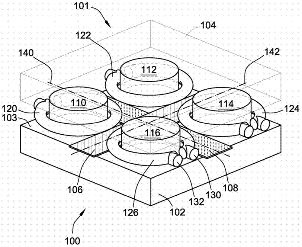
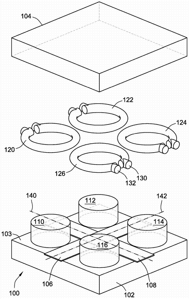
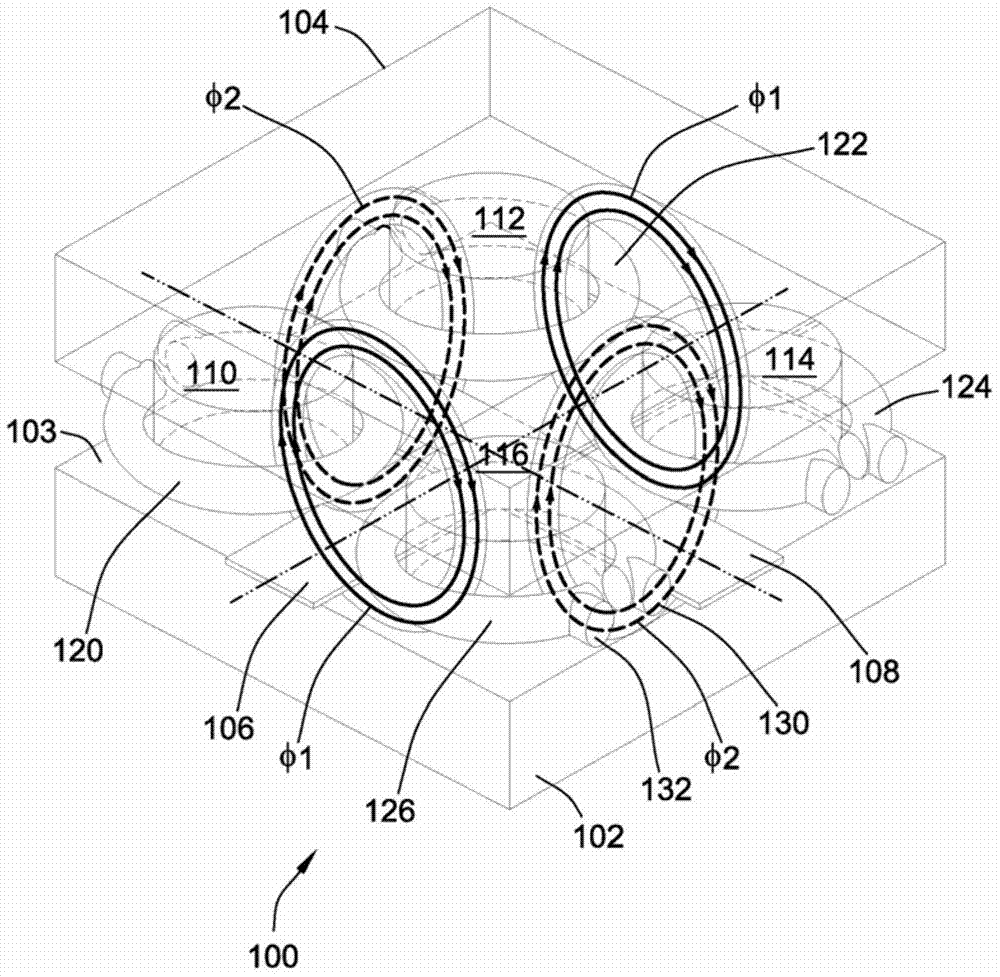
[0050] figure 1An assembled perspective view of the integrated magnetic component 100 according to the first embodiment of the present invention is shown. Integrated magnetics 100 includes a magnetically permeable core 101 having a base member 102 and a top member 104 . The base member 102 includes a first leg 110, a second leg 112, a third leg 114 and a fourth leg 116, all of which protrude substantially perpendicularly from the base member 102 to the lower surface of the top member such that the top member is respectively attached to Opposite ends o...


PUM


Abstract

The present invention relates to an integrated magnetic component comprising a magnetically permeable core. The magnetically permeable core comprises a base member extending in a horizontal plane and first, second, third and fourth legs protruding substantially perpendicularly from the base member. First, second, third and fourth output inductor windings are wound around the first, second, third and fourth legs, respectively. A first input conductor of the integrated magnetic component has a first conductor axis and extends in-between the first, second, third and fourth legs to induce a first magnetic flux through a first flux path of the magnetically permeable core. A second input conductor of the integrated magnetic component has a second coil axis extending substantially perpendicularly to the first conductor axis to induce a second magnetic flux through a second flux path of the magnetically permeable core extending substantially orthogonally to the first flux path. Another aspect of the invention relates to a multiple-input isolated power converter comprising the integrated magnetic component.

Description

technical field [0001] The present invention relates to an integrated magnetic element comprising a magnetically permeable core comprising a base member extending in a horizontal plane and first, second, third and third legs protruding substantially perpendicularly from the base member. four legs. The first output inductor winding, the second output inductor winding, the third output inductor winding and the fourth output inductor winding are respectively wound around the first leg, the second leg, the third leg and the fourth leg. A first input conductor of the integrated magnetics has a first coil axis and extends between first, second, third and fourth legs to induce a first magnetic flux path through the magnetically permeable core. A magnetic flux. The second input conductor of the integrated magnetics has a second coil axis extending substantially perpendicular to the first coil axis to induce a second magnetic flux through a second flux path of the magnetically permea...

Claims


Application Information

Patent Timeline
Patent Type & Authority Applications(China)
IPC IPC(8): H01F27/38H01F30/06H02M3/335H01F38/00
CPCH02M3/285H01F27/38H01F27/28H01L28/10H02M1/0064H01F30/06H01F38/00H02M3/335H02M3/33546
Inventor 欧阳紫薇迈克尔·A·E·安德森张哲
Owner DANMARKS TEKNISKE UNIV
Why Eureka
Try Eureka