Dust suction pipe raising ring

A vacuum tube and height-adjusting technology, which is used in vacuum cleaners, cleaning equipment, household appliances, etc., can solve the problems of reduced suction power and lack of flow of the vacuum tube.

Inactive Publication Date: 2014-05-14
KUNSHAN MAX METAL
View PDF6 Cites 0 Cited by
  • Summary
  • Abstract
  • Description
  • Claims
  • Application Information

AI Technical Summary

Problems solved by technology

[0002] The original vacuum pipe height adjustment ring is easy to reduce the suction force of the vacuum pipe due to insufficient height adjustment during the use of the vacuum pipe; the lack of flow has many defects; a device is urgently needed to solve this problem

Method used


Image

  • Dust suction pipe raising ring

Examples


Embodiment Construction

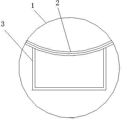
[0013] Such as figure 1 As shown, a vacuum pipe height adjustment ring, the dust suction pipe height adjustment ring includes an outer ring 1, a mesh plate 2, and a steel pipe 3, and the outer ring 1 is made of flat iron and has a circular structure. The screen plate 2 is made of Yuan Gang and is connected with the outer ring 1 and made into one body, and the steel pipe 3 is connected to the screen plate 2 and the outer ring 1 .

[0014] The above is only one of the specific embodiments of the present invention, but the scope of protection of the present invention is not limited thereto, and any person familiar with the art can think of it without creative work within the technical scope disclosed in the present invention. Changes or substitutions should fall within the protection scope of the present invention. Therefore, the protection scope of the present invention should be determined by the protection scope defined in the claims.


PUM


Abstract

The invention relates to a dust suction pipe raising ring. The dust suction pipe raising ring comprises an outer ring, a screen plate and steel pipes. The outer ring is made from flat iron and is of a circular structure. The screen plate is made from round steel, the screen plate is connected with the outer ring, and the screen plate and the outer ring are manufactured into a whole. The steel pipes are connected to the screen plate and the outer ring. The dust suction pipe raising ring solves the problem that an existing dust suction pipe is not high enough.

Description

technical field [0001] The invention relates to a height-adjusting ring for a dust suction pipe. Background technique [0002] The original vacuum pipe height adjustment ring is easy to reduce the suction force of the vacuum pipe due to insufficient height adjustment during the use of the vacuum pipe; the lack of flow has many defects; a device is urgently needed to solve this problem. Contents of the invention [0003] The technical problem to be solved by the present invention is to provide a height-adjusting ring for a dust suction pipe to realize height adjustment of the dust suction pipe during use. [0004] The technical problem to be solved can be implemented through the following technical solutions. [0005] A height-adjusting ring for a dust suction pipe, characterized in that the height-adjusting ring for a dust suction pipe includes an outer ring, a mesh plate, and a steel pipe. [0006] As a further improvement of the technical solution, the outer ring is ma...

Claims


Application Information

Patent Timeline
IPC IPC(8): A47L9/00
Inventor 王红磊李创
Owner KUNSHAN MAX METAL
Why Eureka
Try Eureka