Hoop tube type air-free tire

A technology for free of pneumatic tires and hoops, which is applied to non-pneumatic tires, special tires, tire parts, etc. It can solve the problems of tires detaching from the rim, uneven tire force, and inappropriateness, so as to facilitate the installation and removal of tires , small rolling resistance, suitable for high speed

Active Publication Date: 2017-07-18
HUAWEI TEHCHNOLOGIES CO LTD
View PDF1 Cites 0 Cited by
  • Summary
  • Abstract
  • Description
  • Claims
  • Application Information

AI Technical Summary

Problems solved by technology

[0002] The first major defect of the existing air-free tires is that the tire hoop is not tight enough to the rim, causing the tire to detach from the rim and slide relative to the rim, which is not suitable for high-speed use. The second major defect is the uneven deformation and collapse inside the tire. It leads to uneven and enlarged tire contact surface, vehicle vibration and increased rolling resistance
For example, the patent No. 200810072351.8 new air-free tire also has these two major defects. One is that it does not set and mention the components for the tire to tighten the rim. In this way, the impact on the radial expansion and contraction of the inner side of the tire ring is almost zero, and it does not contribute to the tightening of the tire on the rim. Second, there is a gap between the inner ring tube and other components. The gap is filled with filling material. The outer periphery of the filling material, the positioning device, and the circular steel ring are all covered with mesh. In this way, when the tire is stressed, the filling material is squeezed and displaced and the mesh is deformed, resulting in inner and outer tires. Concave-convex and subsidence appear between the tires, the force on the tire is uneven, and the rolling resistance increases. In addition, it is difficult to limit the position of the steel hoop with the mesh covering filler of this technology, and the position error of the positioning column installed on the steel hoop will be large. The probability of the positioning column being randomly inserted into the mold hole tends to be zero. Perhaps because of this, no samples of this patented technology have been released so far. It can be seen that this patented technical solution is not a question of whether it is good or not, but a question of whether it works.

Method used


Image

  • Hoop tube type air-free tire
  • Hoop tube type air-free tire
  • Hoop tube type air-free tire

Examples


Embodiment 1

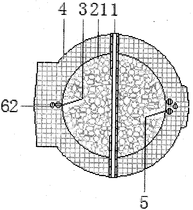
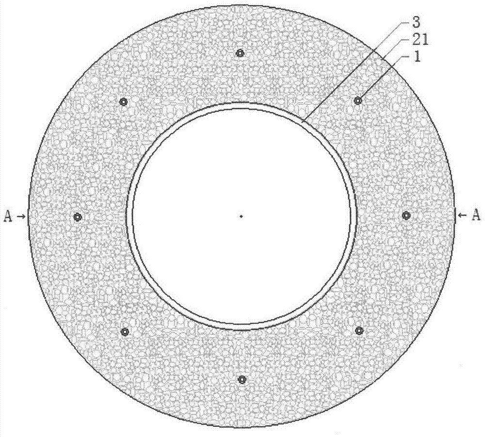
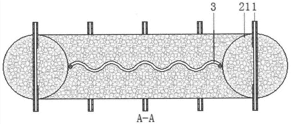
[0007] Embodiment one, such as figure 1 , figure 2 , Figure 5 , Image 6 , Figure 7 As shown, a bubble body ring tube 21 with a circular cross section has eight tire support tubes 1 across and fixed on both sides of the ring at equal intervals, and the two ends of each tire support tube 1 protrude from the bubble body. Outside the two sides of the ring of the circular pipe ring 21, a laterally wavy elastic hoop 3 is fixed on the inner side of the ring to form the inner tube of the hoop. On the ring side, the so-called weft hoop inner tube is formed, and the polymer material is poured into the mold cavity of the weft hoop inner tube supported by the two ends of each tire support tube 1 to form the connected outer tube 4, and the hoop inner tube type is obtained. Free air tires. The foam ring tube 21 is made of polymer material such as PU foam, and the surface can be made into a smooth arc, or can be made to match the grooves of the hoop and interconnected elastic parts....

Embodiment 2

[0008] Embodiment two, such as figure 1 , figure 2 , Figure 5 , Image 6 , Figure 8 As shown, at least three non-closed single elastic rings 61 are nested at equal intervals on the tube surface of the weft hoop inner tube of embodiment 1. Others are the same as in Embodiment 1.

Embodiment 3

[0009] Embodiment three, such as figure 1 , figure 2 , Figure 5 , Image 6 , Figure 9 As shown, a helical tube spring 62 is sheathed at equal pitches on the tube surface of the weft hoop inner tube of embodiment 1, and the connection at both ends is preferably clamped by inserting tube sections. Others are the same as in Embodiment 1.


PUM


Abstract

The invention provides a hoop inner tube type non-pneumatic tire. The tire comprises an inner tube and an outer tube which are connected with each other; at least three tire supporting pipes transversally pass through, at an equal interval, and are fixed on the two sides of a circular pipe ring with a circular cross section, and two end sections of each tire supporting pipe extend out of the two sides of the circular pipe ring; at least one elastic hoop with a waved lateral profile is fixedly arranged at the inner side of the circular pipe ring to form a hoop inner tube; interconnected elastic parts are sleeved and a connected outer tube is cast on the surfaces of parts, where no tire supporting pipes are arranged, of the hoop inner tube from the inside to the outside in sequence. The elastic hoop of the tire has good extension and contraction performance, which facilitates mounting and dismounting of the tire and enables the tire to be hooped on a rim tightly; the tire supporting pipes are simple and easy to manufacture and accurate to position; the inner tube and the outer tube are connected, bumps and collapse do not exist, and only two molds are needed for integrated forming; and thus, the hoop inner tube type non-pneumatic tire has the advantages of low possibility of tire separation, small rolling resistance and suitability for high speed running and the like. A sample of the hoop inner tube type non-pneumatic tire provided by the invention has been manufactured.

Description

technical field [0001] The invention relates to the invention of air-free tires, especially hoop inner tubes and air-free tires Background technique [0002] The first major defect of the existing air-free tires is that the tire hoop is not tight enough to the rim, which causes the tire to separate from the rim and slide relative to the rim, which is not suitable for high-speed use. The second major defect is the uneven deformation and collapse inside the tire. As a result, the contact surface of the tire is uneven and enlarged, and the driving vibration and rolling resistance of the whole vehicle increase. For example, the patent No. 200810072351.8 new air-free tire also has these two major defects. One is that it does not set and mention the components for the tire to tighten the rim. In this way, the influence on the radial expansion and contraction of the inner side of the tire ring is almost zero, and it does not contribute to the tightening of the tire on the rim. Sec...

Claims


Application Information

Patent Timeline
Patent Type & Authority Patents(China)
IPC IPC(8): B60C7/00B60C1/00
CPCY02T10/86
Inventor 全解生
Owner HUAWEI TEHCHNOLOGIES CO LTD
Why Eureka
Try Eureka