Eureka AIR delivers breakthrough ideas for toughest innovation challenges, trusted by R&D personnel around the world.

A hydraulic transmission system that allows energy recovery

A technology of hydraulic transmission and energy recovery, which is applied in the direction of fluid pressure actuators, servo motors, mechanical equipment, etc., can solve the problems of weakened braking ability of the brakes when the temperature rises, insufficient driving ability and passing performance, and loss of braking energy, etc., to achieve Good adaptability to working conditions, small structure size, and the effect of improving driving force

Active Publication Date: 2015-09-30
SHANGHAI ZHONGLIAN NENGCHUANG NEW ENERGY TECH CO LTD
View PDF9 Cites 0 Cited by
  • Summary
  • Abstract
  • Description
  • Claims
  • Application Information

AI Technical Summary

Problems solved by technology

[0005] The technical problem to be solved by the present invention is to overcome the problem of insufficient driving ability and passing performance of the target vehicle when the driving wheel slips in the prior art; at the same time, it solves the problems of braking energy loss and brake temperature rise when the target vehicle frequently brakes in the prior art. The problem of reduced dynamic capacity provides a hydraulic transmission system that allows energy recovery

Method used


Image

  • A hydraulic transmission system that allows energy recovery
  • A hydraulic transmission system that allows energy recovery
  • A hydraulic transmission system that allows energy recovery

Examples


Embodiment Construction

[0031] The present invention will be described in detail below in conjunction with the drawings:

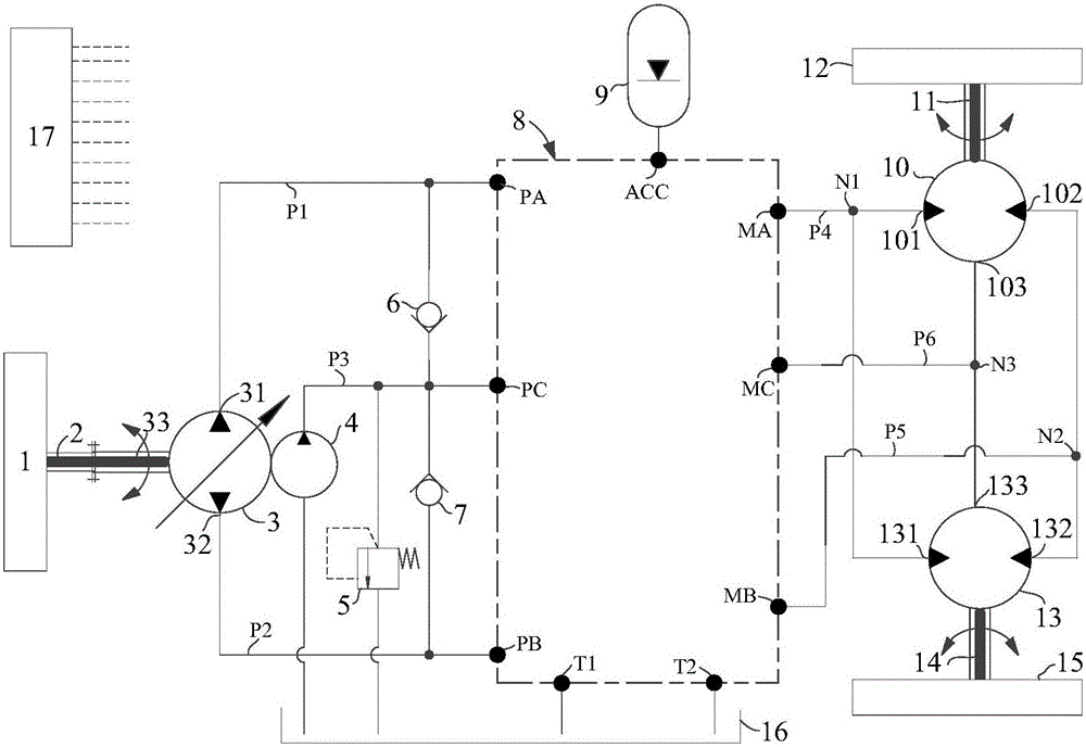
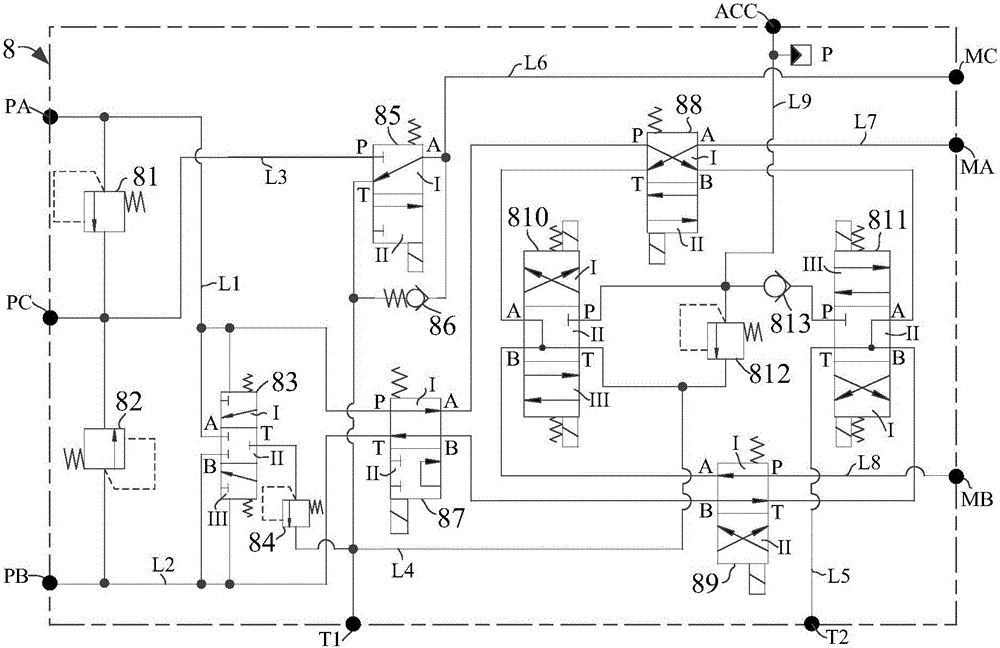
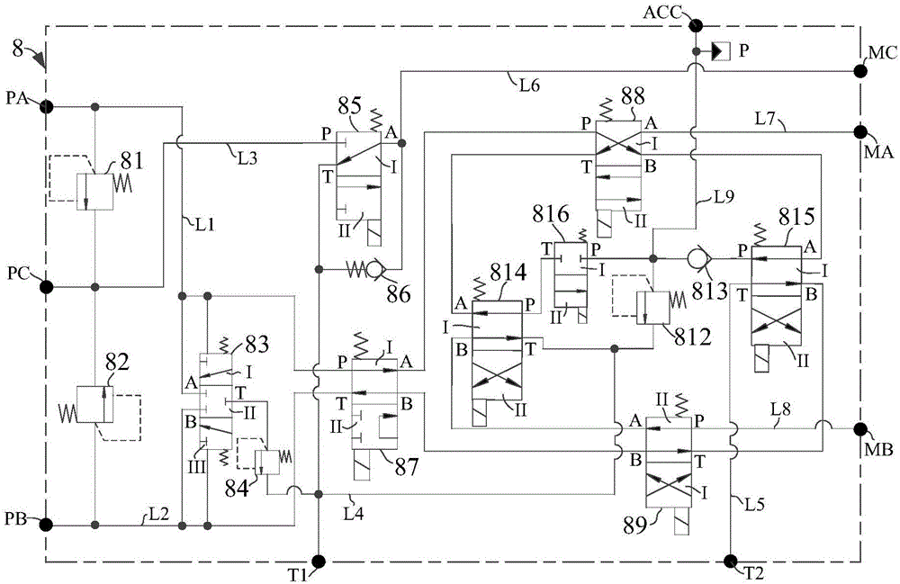
[0032] The purpose of the present invention is to provide a hydraulic transmission system that allows energy recovery. The hydraulic transmission system that allows energy recovery is used in the auxiliary front-wheel drive structure of target vehicles such as heavy construction transportation vehicles, and has a free wheel mode, Pump driving mode, accumulator driving mode, pump and accumulator driving mode, and energy recovery mode; when the driving wheel is slipping, the system of the present invention can provide auxiliary driving force of the target vehicle and improve its driving ability and passing performance; At the same time, when the target vehicle is braking, the lost kinetic energy can be recovered and stored in the accumulator in the form of pressurized oil, and the energy can be released when necessary to assist in driving the target vehicle.

[0033] Refer to figure 1 T...


PUM


Abstract

The invention discloses a hydraulic transmission system enabling energy recovery. The hydraulic transmission system aims to solve the problems that driving ability and passing performance of a target vehicle are not enough when driving wheels slide in the prior art. The hydraulic transmission system comprises a power input mechanism, a hydraulic pump assembly, a control valve group, an energy accumulator, a first hydraulic motor, a load mass body of the first hydraulic motor, a second hydraulic motor, a load mass body of the second hydraulic motor, an oil tank and a control unit. The power input mechanism is mechanically connected with the hydraulic pump assembly, the hydraulic pump assembly is connected with the control valve group through a pipeline, the control valve group is sequentially connected with the first hydraulic motor and the second hydraulic motor through a pipeline, the first hydraulic motor is mechanically connected with the load mass body of the first hydraulic motor, the second hydraulic motor is mechanically connected with the load mass body of the second hydraulic motor, the hydraulic pump assembly and the control valve group are respectively connected with the oil tank through a pipeline, and the hydraulic pump assembly and the hydraulic control valve group are respectively connected with the control unit through a signal line.

Description

Technical field [0001] The invention relates to a device belonging to the field of hydraulic transmission. More specifically, the invention relates to a hydraulic transmission system that allows energy recovery for heavy engineering transportation vehicles. Background technique [0002] The working conditions of heavy engineering transport vehicles are more complex and changeable, and they often run on low-attachment roads or climb long slopes, causing slipping of the driving wheels and insufficient driving force. The solution to this problem is to assist the front-wheel drive structure, and the hydraulic transmission system has the characteristics of simple structure, high specific power, low modification cost, and mature technology development. It is commonly used in the field of engineering vehicles. At the same time, the radial plunger hydraulic motor It is small in size and can be installed in the hub of the front wheel. It does not take up space but also has the characteris...

Claims


Application Information

Patent Timeline
Patent Type & Authority Patents(China)
IPC IPC(8): F15B11/17F15B1/02
Inventor 曾小华李相华宋大凤李高志李胜刘彬娜彭君朱志诚王广义陈顺潇
Owner SHANGHAI ZHONGLIAN NENGCHUANG NEW ENERGY TECH CO LTD
Why Eureka
Eureka Blog
Learn More