Pumping system and fluid delivery installation

a technology of pumping system and fluid delivery, which is applied in the direction of positive displacement liquid engine, piston pump, liquid fuel engine, etc., can solve the problems of increasing installation and use costs, affecting the reliability of pumping system, etc., to achieve the effect of high fluid delivery pressure and increased reliability

Pending Publication Date: 2022-04-21
WAN HOI ARMAND
View PDF8 Cites 0 Cited by
  • Summary
  • Abstract
  • Description
  • Claims
  • Application Information

AI Technical Summary

Benefits of technology

[0017]The aim of the invention is to provide a pumping system with increased reliability at high fluid pressures, and thus generate a sufficiently high fluid delivery pressure in order to enable, in particular, uses for handling the delivered fluid.

Problems solved by technology

The supply water to mountainous areas or plateaus with no water resources constitutes a major problem for the inhabitants of these areas.
However, although such delivery pumps are energy efficient, installing and using them incur significant costs.
However, the use of a hydraulic ram is not always satisfactory and has some drawbacks such as the noise generated by the “water hammer”, the need to make complex adjustments during installation, or otherwise a weak and choppy flow rate as well as a limited delivery height with respect to the motorized pumps.
However, such a pump 1000 has drawbacks, in particular with regard to its operating conditions.
Indeed, it is difficult to ensure perfect sealing of the intake and delivery ducts 520, 540, 560, 680, 600, 620 by the distribution carriage, in particular when the fluid pressure becomes large.
In fact, the delivery pressure of the fluid remains limited.

Method used


Image

  • Pumping system and fluid delivery installation
  • Pumping system and fluid delivery installation
  • Pumping system and fluid delivery installation

Examples


first embodiment

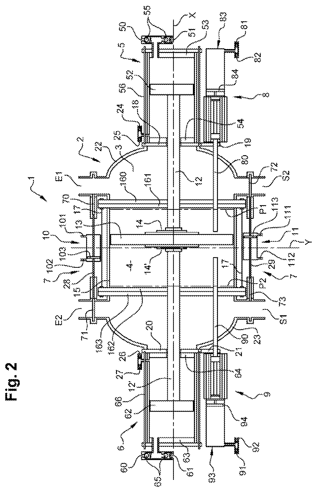
[0054]With reference to FIGS. 2 and 3, the pump 1 in a first embodiment will now be described.

[0055]The pump 1 comprises a drive enclosure 2, preferably having a generally cylindrical shape, extending along a longitudinal axis X. Said drive enclosure 2 is closed at these axial ends by closure elements of the shield type 22, 23. Preferably, as shown in FIG. 2, these two shields 22, 23 are domed to better withstand the pressures exerted by the operating fluid moving in the drive enclosure 2. The drive enclosure 2 is thus formed by a cylindrical wall 15, the ends of which are closed by the domed walls 22, 23.

[0056]The drive enclosure 2 is further made of a metallic or composite material intended to withstand fluid pressures at least equal to three times the pressure of the pressure column.

[0057]The domed shields 22, 23 and the cylindrical portion 15 of the drive chamber 2 are connected together by annular flanges 160-163. Four annular flanges 160-163 are shown in FIG. 2: two flanges 16...

second embodiment

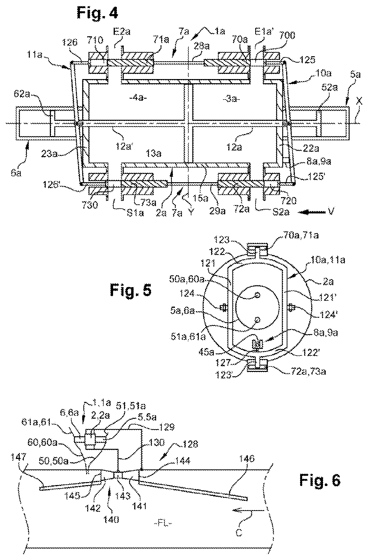
[0129]With reference to FIGS. 4 and 5, the pumping system 1a will now be described.

[0130]The drive enclosure 2a in this second embodiment has an identical shape, at the difference near that the shields 22a, 23a are preferably planar walls.

[0131]The main difference in this second embodiment resides in the activating members 10a, 11a which are in this case two tilting lever members arranged at the shields 22a, 23a of the drive enclosure 2a on either side of a transverse axis Y of said drive enclosure 2a.

[0132]Referring to FIG. 5, each tilting lever 10a, 11a comprises a main portion of a substantially oval shape, with two parallel rectilinear arms 121, 121′ extending in the plane containing the transverse axis Y, on either side of the respective multiplier chamber 5a, 6a. The two arms 121, 121′ of a tilting lever 10a, 11a are connected to one another at their opposite ends by two curved arms 122, 122′.

[0133]Each rectilinear arm 121, 121′ is pivotally connected, at a central portion o...


PUM


Abstract

The invention relates mainly to a pumping system (1) which comprises an alternating distribution device comprising at least one shut-off device (7) comprising four mobile shut-off members (70-73) for shutting off first and second inlets (E1, E2; E1a, E2a) and first and second outlets (S1, S2; S1a, S2a) of the pumping system (1) and at least one trigger (8, 9) configured to actuate said shut-off members (70-73) between two positions, respectively a shutting-off position and an open position, which alternating distribution device can be actuated between a first arrangement associated with a first fluid distribution cycle and a second arrangement associated with a second fluid distribution cycle.

Description

TECHNICAL FIELD[0001]The invention generally relates to a system for delivering a fluid.[0002]More particularly, the invention relates to a pumping system for delivering a fluid, such as water, from a low altitude zone to a higher altitude zone.PRIOR ART AND DRAWBACKS OF THE PRIOR ART[0003]The supply water to mountainous areas or plateaus with no water resources constitutes a major problem for the inhabitants of these areas.[0004]Thus, in order to supply water to areas at altitudes of several hundred meters, delivery pumps driven by combustion engines or electric engines are known to be used. These delivery pumps make it possible to deliver water located at a first area at a low altitude to a second area at a higher altitude. However, although such delivery pumps are energy efficient, installing and using them incur significant costs.[0005]As an alternative to motorized pumps, hydraulic rams are known to be used since installing them is less expensive and require little maintenance....

Claims


Application Information

Patent Timeline
Patent Type & Authority Applications(United States)
IPC IPC(8): F04B9/113F03C1/007F04F7/02
CPCF04B9/113F04F7/02F03C1/007F03C1/0073F04B53/1095
Inventor BIGNON, PIERREWAN-HOI, ARMANDBOUWER, ANTON
Owner WAN HOI ARMAND
Why Eureka
Try Eureka