Piston Pump Having A Force Sensor And A Method For Controlling Said Pump

Inactive Publication Date: 2010-06-10
FLUX INSTR
View PDF22 Cites 11 Cited by
  • Summary
  • Abstract
  • Description
  • Claims
  • Application Information

AI Technical Summary

Benefits of technology

[0007]With low delivery pressures a pulsation of the total delivery flow can thus be completely or nearly avoided, with high and highest delivery pressures, however, a residual pulsation arises. This residual pulsation is caused by the specific compressibility of the pumped medium, which has an increasing effect as the delivery pressure rises and its extent depends on the changing physical properties of the pumped medium. Said residual pulsation may be reduced or suppressed by commencing each delivery cycle with a precompression stroke, which ensures that the medium within the cylinder internal space is compressed to match the respective system pressure prevailing on the high-pressure side prior to the onset of the actual delivery in order to avoid or at least minimize a short-term backflow of pumped medium and / or an interruption of the continuous delivery upon hydraulic transition from one piston to the other.
[0052]In accordance with a particular embodiment of the method according to the present invention, the values or value patterns detected by the sensors are used to correct the efficiency loss in relation to the suction stroke, which arises at the beginning of each suction stroke by expansion of the detrimental dead volume in the displacement area of the piston / cylinder unit compressed during the previous delivery stroke in accordance with the respective specific compressibility of the pumped medium and in accordance with the respective delivery pressure, i.e. the volume, which, due to the design, is inevitably not displaced during the delivery stroke, however, must be compressed prior to the onset of the actual delivery. This is preferably done by a determination of the duration of the decompression phase. The portion of the stroke volume which cannot be displaced from the displacement area of the piston / cylinder unit during each pumping cycle due to expansion of the detrimental dead volume is monitored. The non-usable portion of the suction stroke results from the expansion of the detrimental dead volume. In particular, during low pressure gradient operation, i.e. when the composition of the medium to be delivered changes and subsequently varying compressibility and / or viscosity affects the back-pressure. This is of particular advantage at very high delivery pressures, since the gradient composition of the medium flowing into the pump during the subsequent suction strokes can be adjusted in accordance with the extent of expansion of the detrimental dead volume. Preferably, this is done by opening and closing the solenoid valves usually employed for this purpose in an adaptively controlled manner at the inlet of the pump for each subsequent suction stroke.

Problems solved by technology

Under such operating conditions, the pumped medium no longer behaves as an ideal, i.e. incompressible liquid.
A crucial inherent disadvantage of all feedback controls for compensation of compressibility (pressure feedback), which are based on a qualitative and / or quantitative utilization of the measurement of the delivery pressure, is the need for an iterative adjustment (PID control) within a series of cam revolutions / pumping cycles and a practically limited robustness of the control upon occurrence of pressure artefacts, since only an indirect and no direct monitoring of the process of displacement of the pumped medium is possible by the pressure measuring signal.
Specific technical problems arise with the pressure measuring sensors as well as with the flow sensors from the fact that they must be suited to a very wide measuring range of 0-100 MPa for example and thus, must be able to withstand the high pressure and be peripherally sealable with acceptable effort.
In the case of flow sensors it is of particular disadvantage that the measuring signal is dependent upon the operating temperature as well as the specific thermal conductivity / capacity of the respective medium to be delivered and that consequently, a multiparametric calibration with regard to application is necessary, which can be achieved during operation of the pump in accordance with the low-pressure gradient method at best by a detour via the method of a learning-in run by which a set of reference values is assessed under real analysis run conditions.
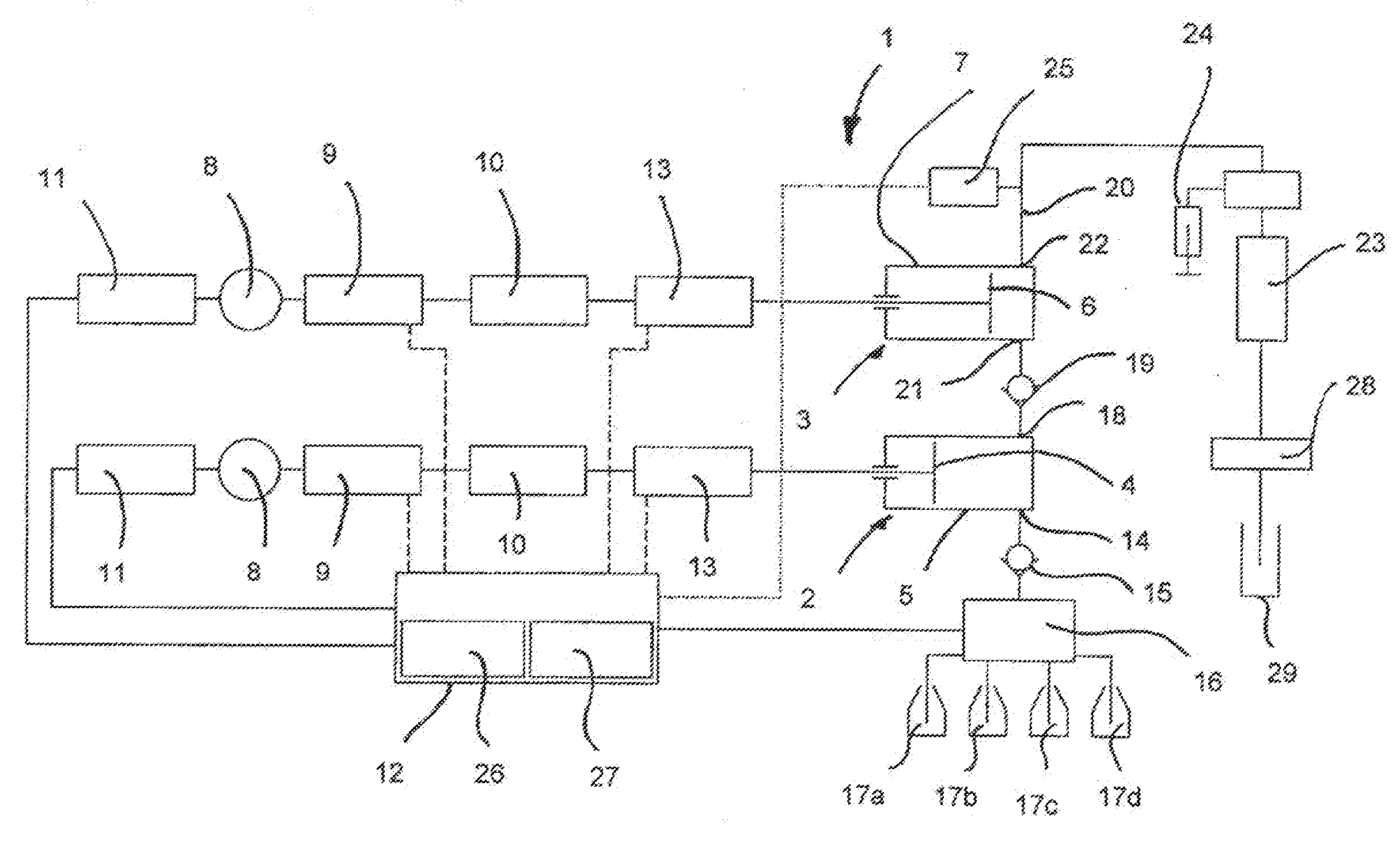
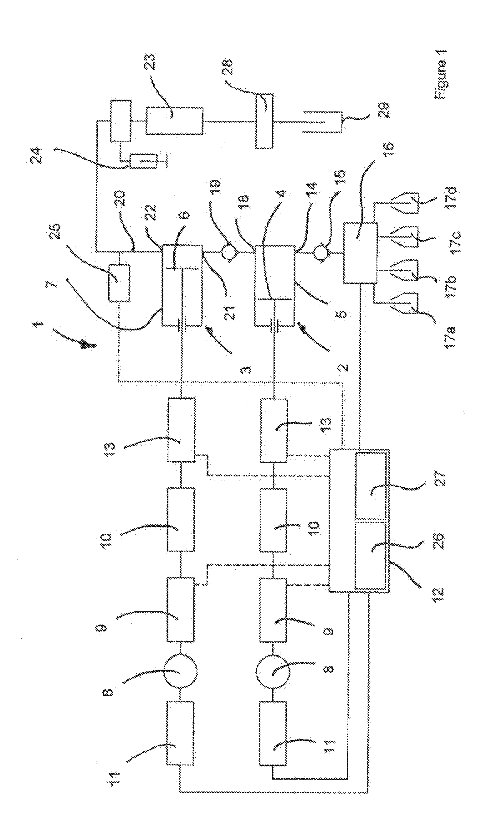
The difficulties described above with regard to design concept superimpose the basic systematic problem of the decrease of the pumping efficiency by detrimental dead volume within the displacement system (piston / cylinder unit) of the working piston when considering the case of a serial dual-piston pump.
Implementing the concept of all-in / all-out, which theoretically presents a solution to the problem, has technical limitations as to the respective design of the components belonging to the displacement chamber feasible in practice.
With increasing delivery pressure, the compressibility of the medium to be delivered causes an increasing drop of the pumping efficiency and associated with that a delivery flow having a more or less pronounced residual pulsation.
The pumping efficiency is diminished solely as a function of the detrimental dead volume, which is technically difficult to minimize, and not as a result of the compression of the (actual) pumping volume during the displacement stroke.
When using the pump while applying the low-pressure gradient methodology, the detrimental dead volume also affects the proportionating of the individual feed flows caused by the proportionating valves on the suction side of the pump.
This causes a reduction in the filling stroke efficiency a problem not addressed by the pumps of the prior art discussed above.
If no sensor has to be arranged in the zone wetted by the pumped medium, there is no need for integrating sensors, which are usually two-dimensional rather than desirably tubular-shaped and which also have to be chemically inert depending on their use, which integration in a fluid-tight manner at high pressure is technically complicated and costly.
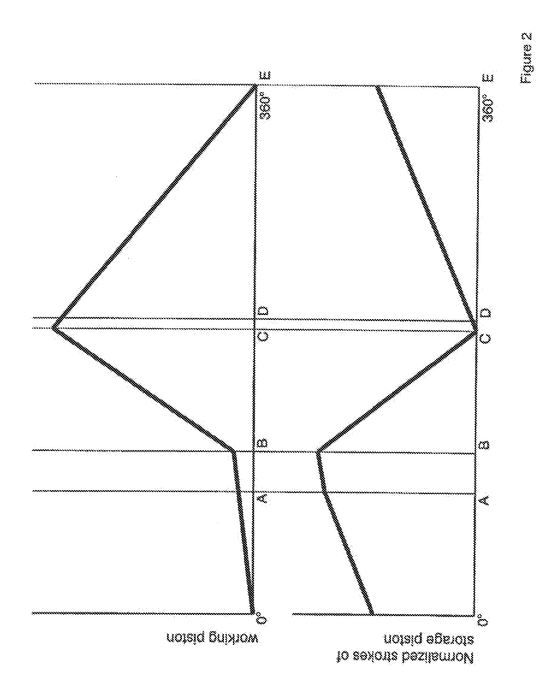
By means of the described pre-compression and / or modulation of the drive speed (primary control) which results in a modulation of the piston speed, an excessive delivery in relation to the previously chosen nominal delivery amount will take place.
The non-usable portion of the suction stroke results from the expansion of the detrimental dead volume.
In particular, during low pressure gradient operation, i.e. when the composition of the medium to be delivered changes and subsequently varying compressibility and / or viscosity affects the back-pressure.

Method used


Image

  • Piston Pump Having A Force Sensor And A Method For Controlling Said Pump
  • Piston Pump Having A Force Sensor And A Method For Controlling Said Pump
  • Piston Pump Having A Force Sensor And A Method For Controlling Said Pump

Examples


Embodiment Construction

[0068]An exemplary embodiment of the piston pump according to the present invention is shown in FIG. 1. The pump 1 designed according to the serial delivery principle comprises a working piston / cylinder unit 2 and a storage piston / cylinder unit 3. The working piston / cylinder unit 2 essentially consists of a working piston 4 performing a reciprocating movement within the cylinder space of a working cylinder 5. Similarly, the storage piston / cylinder unit 3 consists of a storage piston 6 performing a reciprocating movement within the cylinder space of a storage cylinder 7. The working piston 4 and the storage piston 6 are each driven by a separate drive unit. As is apparent from FIG. 1, both drive units are identical, therefore, only the drive unit of the working piston 4 is explained in detail in the following. The explanations equally hold true for the storage piston 6.

[0069]The drive unit of the working piston 5 comprises a motor 8. In principle, any kind of motor may be used as mot...


PUM


Abstract

The present invention relates to a piston pump for generating a delivery flow, which is substantially free of pulsation, in particular to a dual piston pump, and to a method for controlling such a piston pump delivering a pumped medium from a low-pressure area into a high-pressure area, wherein measuring sensors detecting mechanical forces or moments transmitted by the structure of the pump or its associated drive unit are used instead of the pressure or flow sensors usually employed for this purpose.

Description

FIELD OF THE INVENTION[0001]The present invention relates to a piston pump for generating a delivery flow which is substantially free of pulsation, in particular to a dual-piston pump, and to a method for controlling such a piston pump delivering a pumped medium from a low-pressure area into a high-pressure area.BACKGROUND OF THE INVENTION[0002]A piston pump according to the present invention comprises at least two piston / cylinder units for delivering the pumped medium from a low-pressure area into a high-pressure area, a cam drive for driving at least one piston / cylinder unit, a control unit for controlling the rotational speed of the cam drive, and a sensor for measuring an actual value of a control parameter, by which actual value the extent of pulsation of the delivery flow generated on the high-pressure side can be derived.[0003]Pumps of this kind are employed, for example, in liquid chromatography, especially in high-pressure liquid chromatography (HPLC) and in ultrahigh-press...

Claims


Application Information

Patent Timeline
IPC IPC(8): F04B49/00F04B41/06
CPCF04B1/02F04B49/065F04B11/0058F04B11/005
Inventor PREISWERK, THOMASCHAVAN, RENE
Owner FLUX INSTR
Why Eureka
Try Eureka