Unlock instant, AI-driven research and patent intelligence for your innovation.

Gas Valve Unit

A technology of gas valve and valve unit, which is applied in the direction of combustion method, control combustion, combustion equipment, etc.

Active Publication Date: 2014-05-14
BSH BOSCH & SIEMENS HAUSGERAETE GMBH
View PDF11 Cites 1 Cited by
  • Summary
  • Abstract
  • Description
  • Claims
  • Application Information

AI Technical Summary

Problems solved by technology

The disadvantage of this solution is that the cover has to be dismantled before the gas type change and has to be reassembled after the gas type change

Method used


Image

  • Gas Valve Unit
  • Gas Valve Unit
  • Gas Valve Unit

Examples


Embodiment Construction

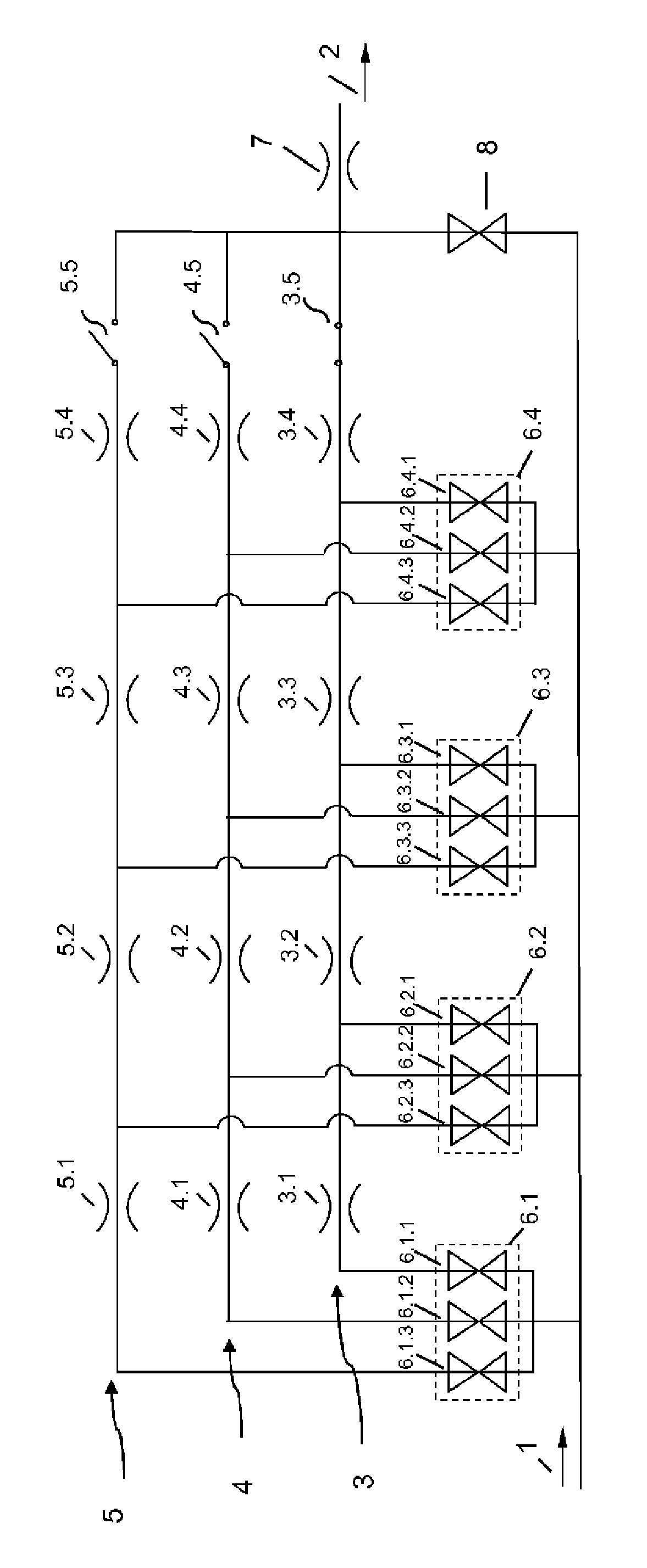
[0044] Figures 1 to 4A schematic switching assembly of the gas valve unit according to the invention is shown in the switching states following one another. A gas inlet 1 can be identified, with which the gas valve unit is connected, for example, to the gas mains of a gas cooking appliance. At the gas inlet 1 there is gas provided for combustion with a constant pressure (for example 20 mbar or 50 mbar). For example, a gas line leading to a gas burner of a gas cooking appliance is connected to the gas outlet 2 of the gas valve unit.

[0045] The gas valve unit has a plurality (N) of throttle sections 3 , 4 , 5 arranged in parallel and individually actuatable for regulating the flow rate of the gas volume flow. The parallel throttling sections 3 , 4 , 5 are arranged between the gas inlet 1 and the gas outlet 2 . Without limitation of generality, in Figures 1 to 4 where N=3.

[0046] The respective throttle section 3 , 4 , 5 has a number M of throttle points 3.1-3.4, 4.1-4...


PUM


Abstract

The subject matter of the invention is a gas valve unit for adjusting a gas flow volume that is fed to a gas burner of a gas-operated device, the gas valve unit having a plurality of, individually actuatable throttle sections arranged in parallel for adjusting the flow rate of the gas flow volume.

Description

technical field [0001] The invention relates to a gas valve unit for regulating a gas volume flow to a gas burner of a gas appliance, in particular a gas cooking appliance. Background technique [0002] Gas valve units of the type mentioned are described, for example, in documents EP0818655A2 and WO2004063629 A1. A gas valve unit of this type can be used to control the gas volume flow to a gas burner of a gas cooking appliance in several stages. In this case, the gas volume flow has a reproducible magnitude in each stage. Overall, the flow cross section of the gas valve unit regulates the magnitude of the gas volume flow by opening or closing a specific switching valve of the gas valve unit and thereby releasing or shutting off the gas flow through a specific throttle opening. [0003] Furthermore, the patent application "Aufbau der Gasventileinheit (Structure of a gas valve unit)" (201002677), not yet published at the filing date, describes a possibility for gas type swit...

Claims


Application Information

Patent Timeline
IPC IPC(8): F23K5/00F23N1/00
CPCF23K5/007F23N1/00F23K2900/05001Y10T137/87249F23N2235/22F23N2235/18F23N2237/08F23N2241/08F23K2400/201F23N1/002
Inventor C.卡多J.瑙曼
Owner BSH BOSCH & SIEMENS HAUSGERAETE GMBH