Abrasive material rotary storage tank device

A storage tank and abrasive technology, applied in the field of abrasive rotating storage tank devices, can solve problems such as inability to convey, and achieve the effect of simple and reasonable structure

Inactive Publication Date: 2014-05-21
CHINA UNIV OF PETROLEUM (EAST CHINA) +1
View PDF6 Cites 4 Cited by
  • Summary
  • Abstract
  • Description
  • Claims
  • Application Information

AI Technical Summary

Problems solved by technology

[0002] In the usual rotary storage tank, the material is stirred and stored after entering the storage tank, and then transported for use. It cannot be transported to the storage tank at the same time as the material is output.

Method used


Image

  • Abrasive material rotary storage tank device

Examples


Embodiment Construction

[0014] The present invention will be further described below in conjunction with accompanying drawing:

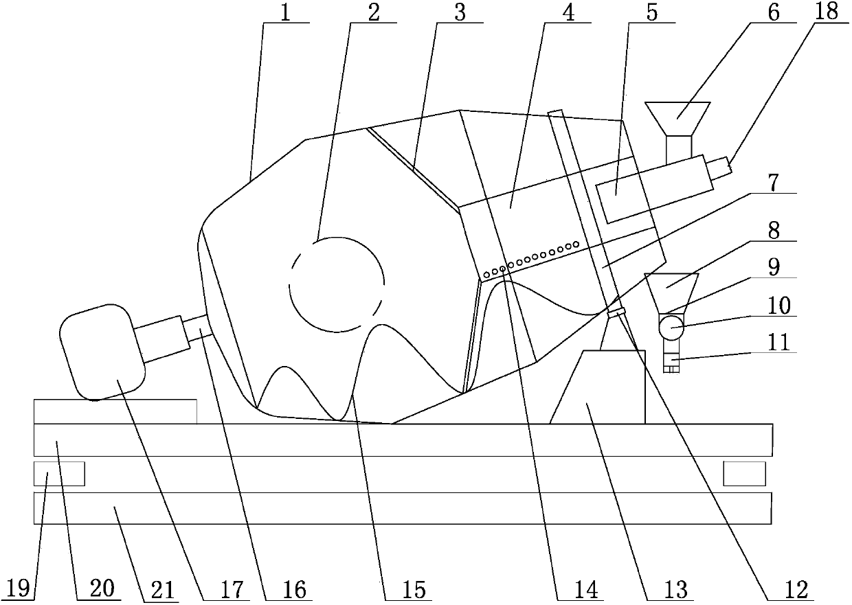
[0015] Such as figure 1 As shown, the abrasive rotary storage tank device of the present invention includes a storage tank, and the storage tank includes a tank body 1. One end of the tank body 1 is connected to a hydraulic drive device 17 through a transmission shaft 16, and a slide rail 7 is arranged on the outer periphery of the other end, corresponding to the slide rail 7. The rail 7 is provided with a pulley 12, and the pulley 12 is installed on the storage tank support 13. A guide cylinder 5 is arranged at the opening end of the tank body 1, and a feeding funnel 6 is arranged on the upper part of the outer end of the guide cylinder 5, and the inner end is placed in the sieve cylinder 4. 4 is located in the tank body 1, screen holes 14 are distributed on the wall of the screen cylinder 4, the bottom periphery is connected to the screen cylinder support frame 3, and the...


PUM


Abstract

The invention belongs to the field of a drilling fluidic device and particularly relates to an abrasive material rotary storage tank device. The abrasive material rotary storage tank device comprises a storage tank; the storage tank comprises a tank body; one end of the tank body is connected with a hydraulic driving device by a transmission shaft and the periphery of the other end of the tank body is provided with a slide rail; corresponding to the slide rail, a sliding wheel is arranged; the sliding wheel is arranged on a storage tank bracket; the open end of the tank body is provided with a guide cylinder; the upper part of the outer end of the guide cylinder is provided with a feeding hopper; the inner end of the guide cylinder is arranged in a screen drum; the screen drum is positioned in the tank body; sieve pores are distributed on the drum wall of the screen drum; the periphery of the bottom of the screen drum is connected with a screen drum support frame; one side of the screen drum is provided with a conveying blade; both the screen drum support frame and the conveying blade are arranged on the inner wall of the tank body; corresponding to the tail end of the conveying blade, the tank body is provided with a discharge port; a buffer hopper is arranged below the discharge port; the bottom of the buffer hopper is provided with a screw conveyor; the screw conveyor is arranged on a conveyor bracket. The abrasive material rotary storage tank device has a simple and reasonable structure, can simultaneously implement rotary feeding and conveying works, can accurately control the conveying amount of abrasive materials and has a great effect on recycling of the abrasive materials.

Description

technical field [0001] The invention relates to an abrasive rotary storage tank device, which belongs to the field of drilling jet devices. Background technique [0002] In the usual rotary storage tank, the material is stirred and stored after entering the storage tank, and then transported for use. It cannot be transported to the storage tank at the same time as the material is output. In abrasive jet drilling, abrasives need to be continuously added to the jet and recycled. The whole process is continuous and uninterrupted, requiring abrasives to be transported to a rotating storage tank for storage while being output. Contents of the invention [0003] The technical problem to be solved by the present invention is to provide an abrasive rotary storage tank device with simple and reasonable structure, convenient use, simultaneous feeding and conveying, and precise control of conveying volume. [0004] The abrasive rotary storage tank device according to the present inv...

Claims


Application Information

Patent Timeline
Patent Type & Authority Applications(China)
IPC IPC(8): B65D88/58B65D90/10B65D90/12B65D90/48B65G65/46B07B1/04E21B7/18
Inventor 周毅汪海阁查永进程荣超纪国栋徐依吉王瑞英李建波李庆陆黄泽超蔡春雷
Owner CHINA UNIV OF PETROLEUM (EAST CHINA)
Why Eureka
Try Eureka