A push-type lid switch locking device

A locking device and cover switch technology, applied in the direction of building fastening devices, wing leaf fastening devices, centrifuges, etc., can solve problems such as safety risks, low efficiency, cumbersome operation, etc., to reduce work intensity and improve Effects of Ease of Use and Security

Active Publication Date: 2016-03-02
SICHUAN NIGALE BIOTECH
View PDF4 Cites 0 Cited by
  • Summary
  • Abstract
  • Description
  • Claims
  • Application Information

AI Technical Summary

Problems solved by technology

Therefore, the cover switch locking device of the existing centrifuge is inefficient and cumbersome to operate
[0004] In addition, the centrifuge is a high-speed rotating device. In the prior art, the observation plate assembly is locked by manually tightening the cover switch. It is also manually judged whether the cover switch is locked and the degree of locking. If the centrifuge is not locked, it will start. When the centrifuge is working or the centrifuge is rotating at a high speed, the observation plate assembly is opened because it is not locked or gradually loosened due to vibration, so there is a great safety risk

Method used


Image

  • A push-type lid switch locking device
  • A push-type lid switch locking device
  • A push-type lid switch locking device

Examples


Embodiment 1

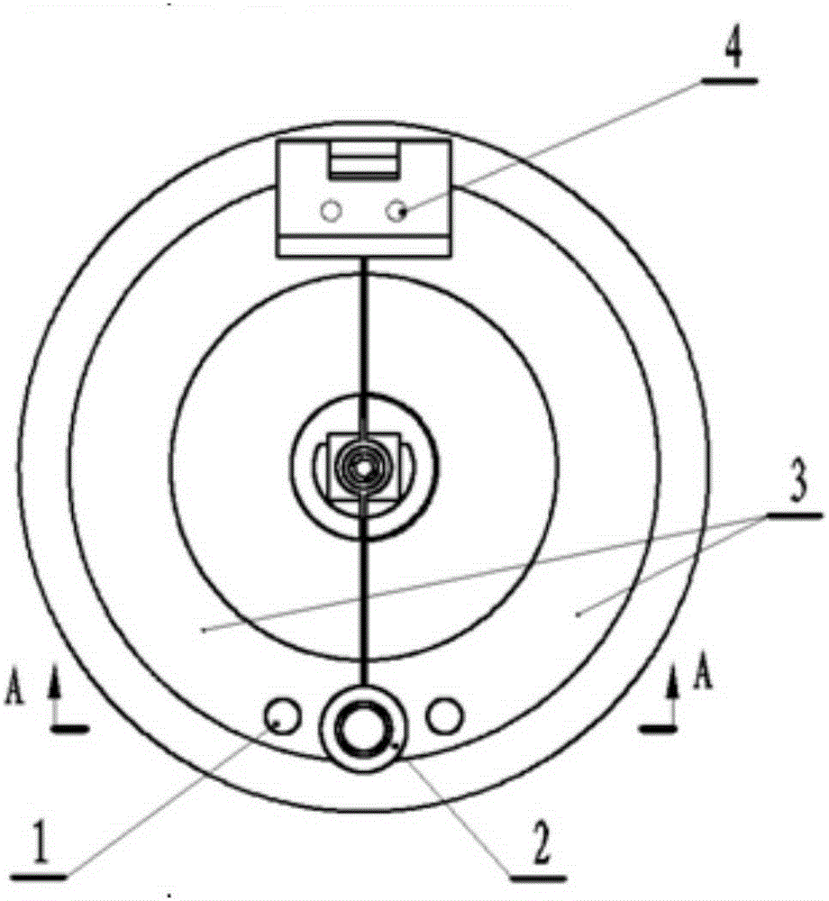
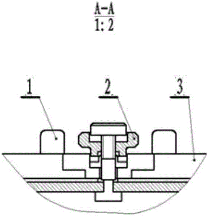
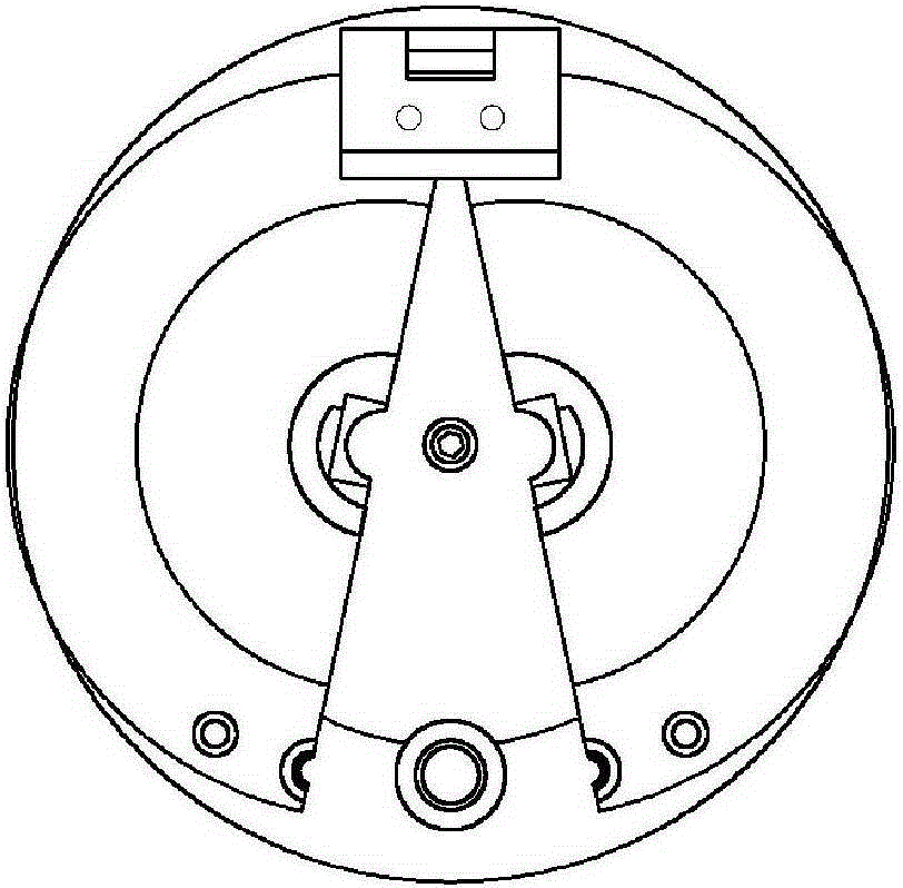
[0055] Such as Figures 1 to 3 As shown, the existing centrifuge cover switch locking device is a screw-type cover switch, such as figure 1 , The lock nut 2 has an internal thread, which can be rotated left and right. Rotate downward to compress the observation plate assembly 3, and rotate upward to loosen the observation plate assembly 3. The left and right halves of the viewing plate assembly 3 can rotate around the rotating pin shaft 4, image 3 It is a schematic diagram of the separation of the two viewing plate assemblies 3 . When the consumables are installed, close the observation plate assembly 3, rotate the lock nut 2, and the lock nut 2 moves down to press the observation plate assembly 2. When the acquisition is completed, rotate the lock nut 2, move the lock nut 2 upwards to loosen the observation plate assembly 3, pull the handle 1, and separate the observation plate assembly 3 to the left and right sides, as image 3 , take out the centrifuge cup consumables....

Embodiment 2

[0057] A push-type cover switch locking device, the locking device is set between the opening and closing joint surfaces of two observation plate assemblies 2, such as image 3 As shown, the observation plate assembly 2 can rotate around the rotating pin shaft 1, and the locking device includes a thrust force that is arranged between the opening and closing joint surfaces of the two observation plate assemblies 2, and always provides a thrust that makes the two have a tendency to open when the two are closed. contact 4. Such as image 3 In the partially enlarged view of , the spring and contact of the thrust contact 4 are embedded in the joint surface of the observation plate assembly 2 . Due to the action of the spring, the thrust contact always pushes the two halves of the observation board assembly 2 to the left and right sides. Two viewing plate assemblies 2 are provided with a handle 17 for pushing respectively. When used in a centrifuge, the two viewing plate assemblie...


PUM


Abstract

The invention discloses a push type cover switch locking device and belongs to the field of lock devices. The push type cover switch locking device comprises a locking device and a thrust contact, wherein the locking device is arranged between opening and closing joint surfaces of two observation plate assemblies; the thrust contact is arranged between the opening and closing joint surfaces of the two observation plate assemblies and always supplies thrust force enabling the two observation plate assemblies to tend to be opened during closing of the two observation plate assemblies; the locking device comprises a movable cover switch assembly, a stationary limiting guide block and a micro-switch; the limiting guide block is matched with the cover switch assembly; the cover switch assembly comprises a cover switch, an elastic piece, a locking contact assembly and an adjusting screw contact assembly; the cover switch is capable of ascending and descending and rotating around the self axis; the elastic piece continuously applies lift force, which enables the cover switch to be in an initial state, to the cover switch; the locking contact assembly is connected with the cover switch and is driven by the cover switch to ascend and descend; the adjusting screw contact assembly is connected with the cover switch and is driven by the cover switch to synchronously ascend and descend and rotate around the self axis. According to the push type cover switch locking device, the usability and the safety are improved, and the labor intensity of an operator is reduced.

Description

technical field [0001] The invention belongs to the field of locking devices, in particular to a locking device used on a cover plate of a centrifuge. Background technique [0002] There is a centrifuge, a key component in the blood collection equipment. The centrifuge is used in conjunction with disposable consumables. The consumables must be replaced every time the blood collection is collected. After the consumables are installed, the centrifuge is locked to start collection. [0003] Existing centrifuge lid switch locking device is the screw type lid switch that uses, as figure 1 , The lock nut has an internal thread and can be rotated left and right. Rotate down to compress the viewing board assembly, and rotate up to loosen the viewing board assembly. The left and right halves of the observation plate assembly can rotate around the pin shaft, figure 2 It is a schematic diagram of the separation of two observation plates. When the consumables are installed, close t...

Claims


Application Information

Patent Timeline
Patent Type & Authority Patents(China)
IPC IPC(8): E05C19/06B04B7/00
Inventor 王鹏廖梓丞黄海涛邹韵
Owner SICHUAN NIGALE BIOTECH
Why Eureka
Try Eureka