A high-negative-pressure area damper assist opening device and manufacturing method
A manufacturing method and a technology for an opening device, which are applied to earth-moving drilling, mine/tunnel ventilation, and mining equipment, etc., can solve problems such as difficulty in opening the air door, achieve simple production and installation, convenient and durable use, and solve the difficulty in opening the air door. Effect
- Summary
- Abstract
- Description
- Claims
- Application Information
AI Technical Summary
Problems solved by technology
Method used
Image
Examples
Embodiment 1
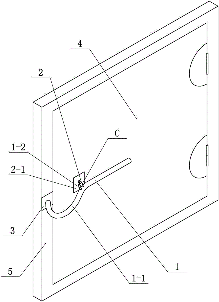
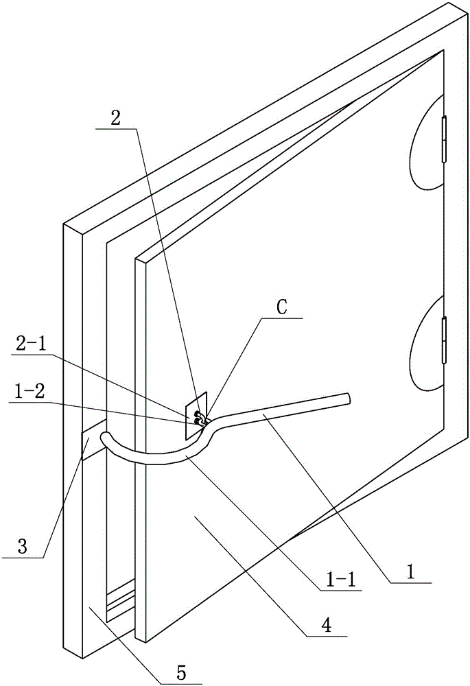
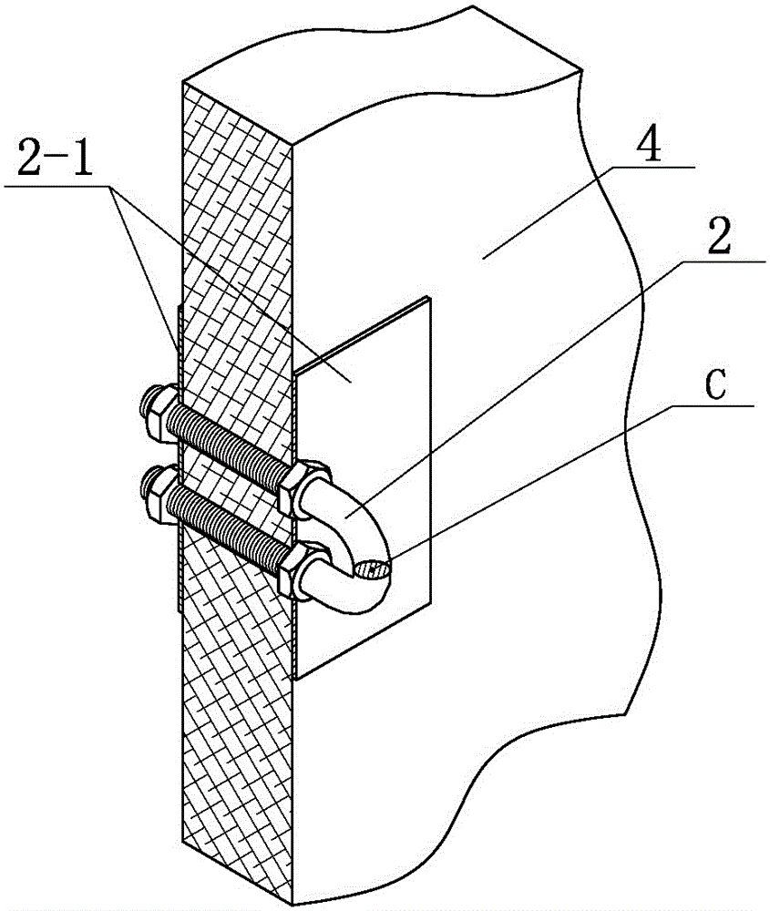
[0028] Such as figure 1 , figure 2 , image 3 , a booster opening device for a damper in a high negative pressure area, installed on the high-pressure side of the damper, including an opening arm 1, a ring seat 2, and a baffle 3, the ring seat is installed on the door leaf 4 of the damper, and the baffle is installed On the door frame 5 of the damper; the opening arm is a lever with a curved elbow 1-1 at the front, and a pull ring 1-2 is arranged on the opening arm; the opening arm is hung on the On the ring seat, and can do lever rotation around the ring seat pivot point C, the top of the opening arm stretches out the door leaf and presses on the baffle plate.
[0029] The cross-sectional shape of the opening arm can be selected as a circle or a hollow circle with an outer diameter of 30 mm to 50 mm,
[0030] The distance from the rear end of the opening arm to the pull ring is 1 to 2 times the distance from the top end of the opening arm to the pull ring.
[0031] The r...
Embodiment 2
[0039] Such as Figure 5 , a method for manufacturing a booster opening device for a damper in a high negative pressure area, the manufacturing method is the manufacturing method for a booster opening device for a damper in a high negative pressure area described in Embodiment 1, so that the opening arm is used on the high pressure side of the damper The lever assist method pulls the door leaf into a gap; in this embodiment, the width D of the door leaf is 1750 mm, and the width E of the door frame is 125 mm; the steps of the manufacturing method are:
[0040] a) Set the gap A=200mm where the door leaf is pulled open;
[0041] b) Determine the section size of the opening arm; the material of the opening arm is DN40 welded steel pipe, and the outer diameter of the section is 40mm;
[0042] c) Set the limit position of the middle point of the top of the opening arm on the end face of the door frame after the door leaf is opened to the gap as the inner limit point P1, and the di...
Embodiment 3
[0052] Such as Figure 6 , this embodiment is an improvement made on the basis of Embodiment 1 or Embodiment 2. For the same parts in this embodiment as Embodiment 1 or Embodiment 2, please refer to the content disclosed in Embodiment 1 or Embodiment 2. It should be understood that the content disclosed in Embodiment 1 or Embodiment 2 should also be used as the content of this embodiment.
[0053] When the opening arm rotates as a lever, the rotation plane and the horizontal plane are provided with an included angle of 0°-75°.
[0054] In this embodiment, when the opening arm rotates as a lever, the rotation plane and the horizontal plane have an included angle RS of 45°; the distance BS from the projection point C of the ring seat pivot point on the door leaf plane to the edge of the door leaf is 198mm, and the door leaf When closed, the distance from the position P3 of the top midpoint of the opening arm on the door frame to the inside of the door frame ES=65mm.
[0055] T...
PUM
 Abstract
Description
Claims
Application Information
 - R&D
- Intellectual Property
- Life Sciences
- Materials
- Tech Scout
- Unparalleled Data Quality
- Higher Quality Content
- 60% Fewer Hallucinations
Browse by: Latest US Patents, China's latest patents, Technical Efficacy Thesaurus, Application Domain, Technology Topic, Popular Technical Reports.
© 2025 PatSnap. All rights reserved.Legal|Privacy policy|Modern Slavery Act Transparency Statement|Sitemap|About US| Contact US: help@patsnap.com


