

Gripping tool for removing a section of casing from a well
a well casing and tool technology, applied in the direction of earth drilling, wellbore/well accessories, sealing/packing, etc., can solve the problems of mandrel displacement, back-up sleeve displacement, and inability to remove at least one slip to the deployed position
- Summary
- Abstract
- Description
- Claims
- Application Information
AI Technical Summary
Benefits of technology
Problems solved by technology
Method used
Image

Examples
Embodiment Construction
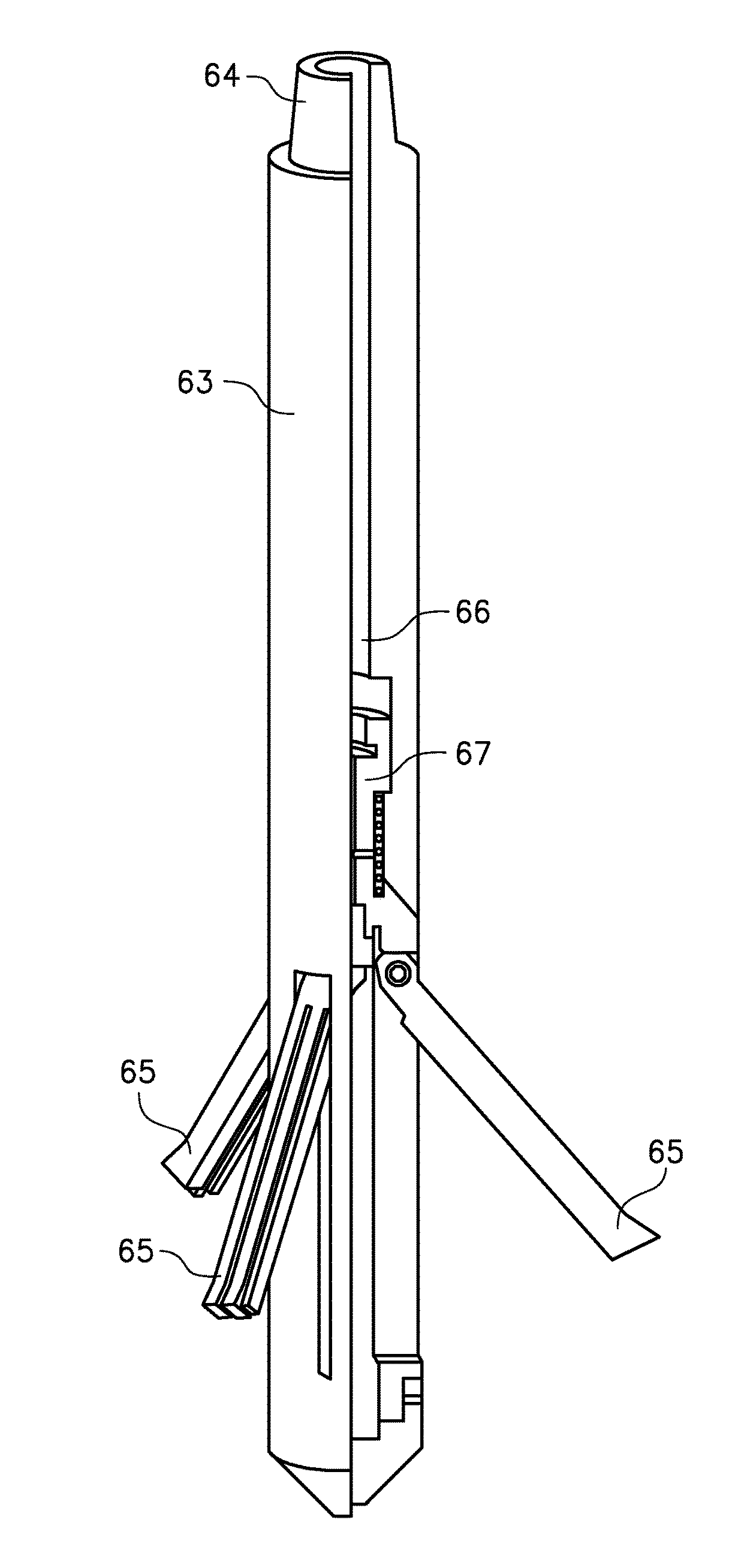
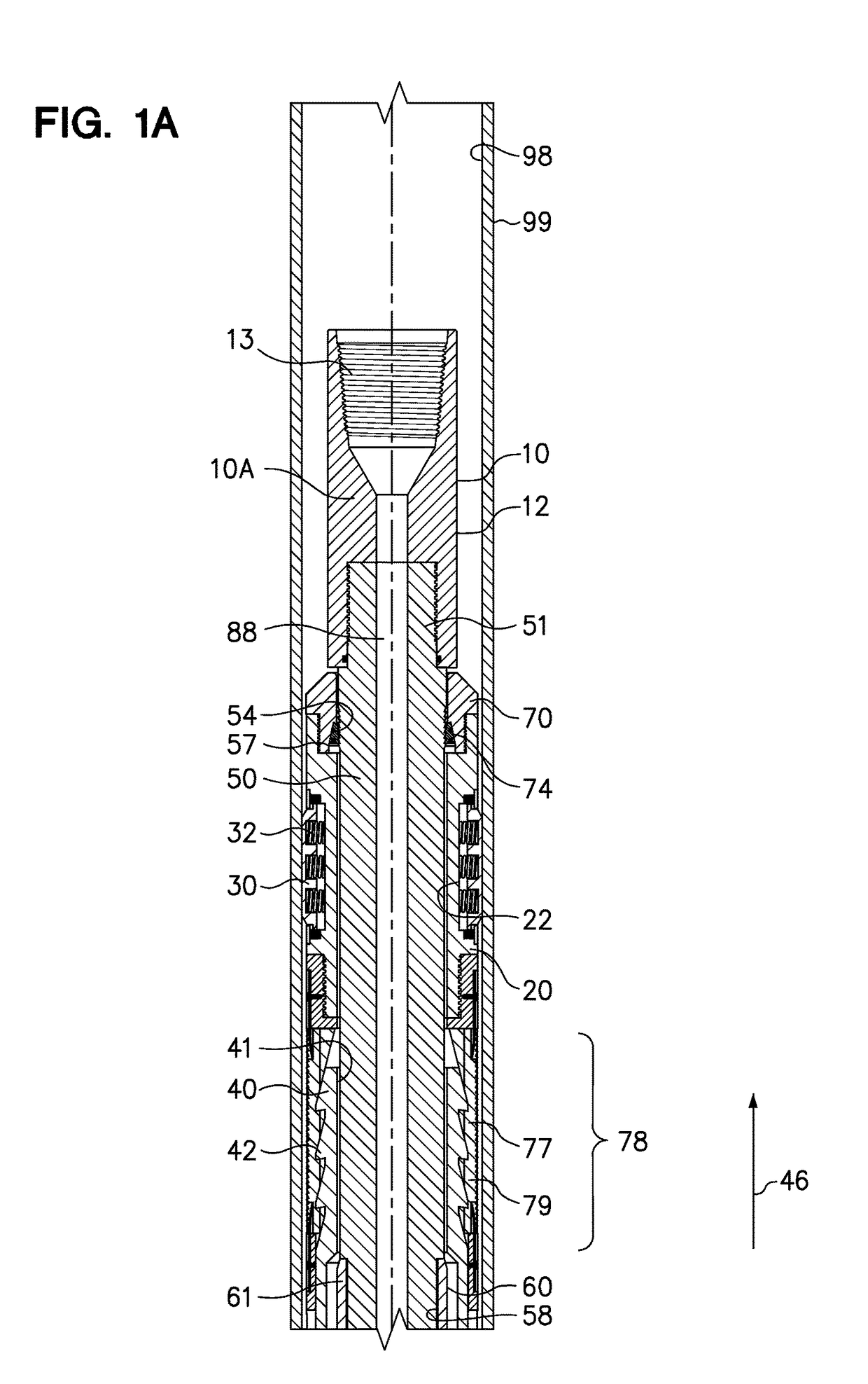
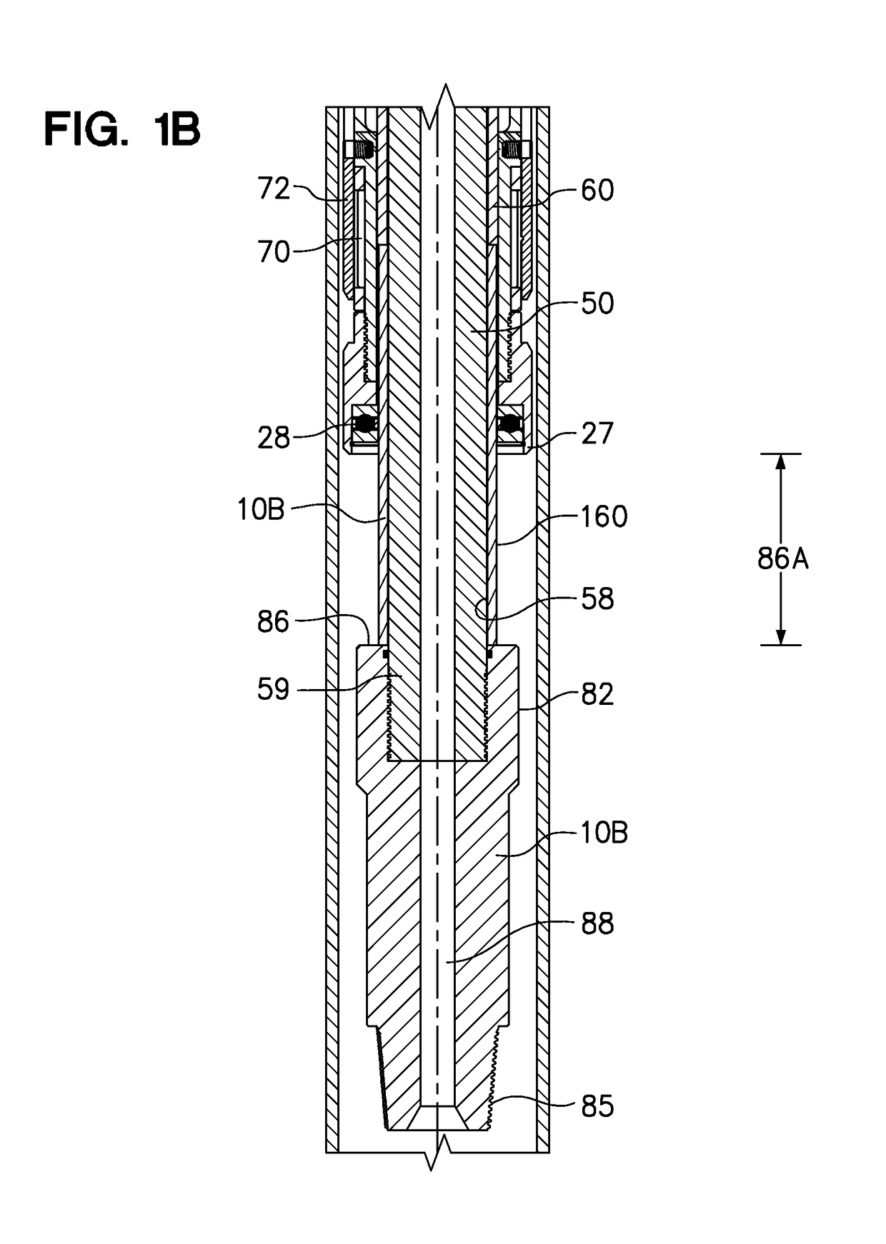
[0040]An embodiment of the casing gripping tool of the present invention provides for rotation of a cutting tool coupled to a distal end of a mandrel of the gripping tool with the gripping tool deployed in a gripping mode to engage and grip an interior wall of a segment of casing targeted for removal from a well. The targeted segment of casing may be a segment of a casing liner that is hung in the wellbore from the top of the casing liner using a liner hanger. An embodiment of the gripping tool of the present invention is adapted to be deployed to grip the section of casing targeted for removal from the wellbore and to simultaneously transmit torque through the mandrel of the gripping tool while the gripping tool remains in the gripping mode to operate a cutting tool coupled to a distal end of the mandrel.
[0041]An embodiment of the gripping tool of the present invention provides for rotation of the mandrel and the cutting tool coupled to the mandrel with the tubular string used to r...
PUM
 Abstract
Description
Claims
Application Information