Contactless power transmission device, contactless power receiving device and contactless power transceiver system

A power receiving device, non-contact technology, applied in circuit devices, electromagnetic wave systems, electric vehicle charging technology, etc., can solve problems such as user troubles, and achieve the effect of reducing maintenance troubles

Inactive Publication Date: 2014-05-21
TOYOTA JIDOSHA KK
View PDF7 Cites 5 Cited by
  • Summary
  • Abstract
  • Description
  • Claims
  • Application Information

AI Technical Summary

Problems solved by technology

[0003] It is cumbersome for users to use a connector to connect an external power supply device to these devices in a wired manner every time these devices are charged or the like.

Method used


Image

  • Contactless power transmission device, contactless power receiving device and contactless power transceiver system
  • Contactless power transmission device, contactless power receiving device and contactless power transceiver system
  • Contactless power transmission device, contactless power receiving device and contactless power transceiver system

Examples


Embodiment approach 1

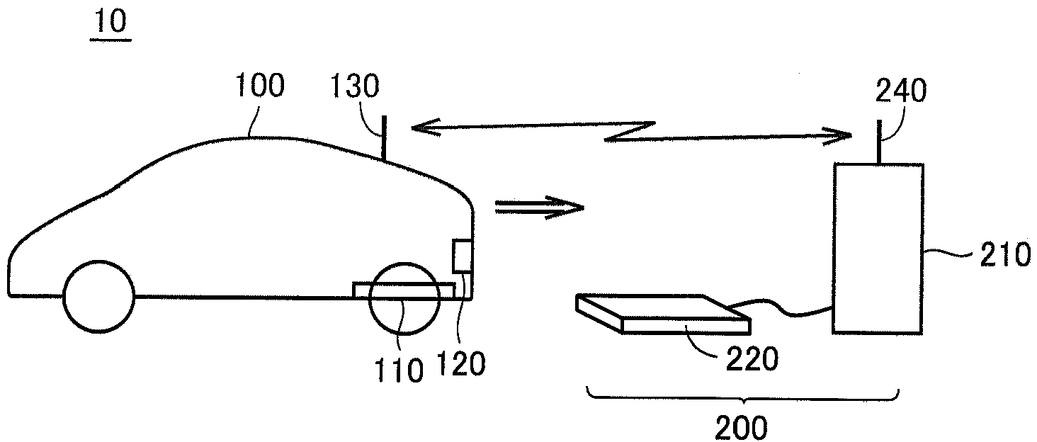
[0064] figure 1 It is an overall configuration diagram of the non-contact power transmission and reception system according to the embodiment of the present invention.

[0065] refer to figure 1 , the non-contact power transmission and reception system 10 includes a vehicle 100 and a power transmission device 200 . Vehicle 100 includes a power receiving unit 110 , a camera (camera) 120 , and a communication unit 130 .

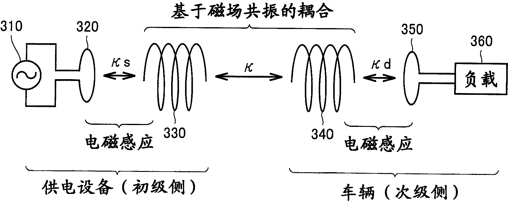
[0066] Power reception unit 110 is provided, for example, on the bottom surface of a vehicle body, and is configured to receive electric power transmitted from power transmission unit 220 of power transmission device 200 in a non-contact manner. Specifically, power receiving unit 110 includes a self-resonant coil described later, and receives electric power from power transmitting unit 220 in a non-contact manner by resonating with the self-resonant coil included in power transmitting unit 220 via an electromagnetic field. Camera 120 is provided to detect th...

Embodiment approach 2

[0180] In Embodiment 1, an example is shown in which a plurality of self-resonant coils are provided on the power transmission device side. Instead of this, a plurality of self-resonant coils may be provided on the power receiving device side. In Embodiment 2, such an example will be described.

[0181] Figure 17 is a diagram showing the configuration of the power receiving unit 110D. Also, for ease of understanding, in Figure 9 The power transmission unit 220D is also shown in .

[0182] The relative positional relationship between the power transmitting unit and the power receiving unit differs depending on the parking position of the vehicle, and it is difficult to require a high-precision parking position every time the vehicle is parked. In addition, in order to standardize the non-contact charging by the resonance method, it is also considered that it is necessary to make the various mounting positions of the power transmission coils of the power receiving device a...


PUM


Abstract

A contactless power transmission device is provided with a plurality of first coils (222A to 222C) for receiving power from an AC power source and transmitting the power to a power receiving device, and a control unit (242) for selecting a coil used for transmitting power to the power receiving device from among the plurality of first coils on the basis of the position of the power receiving device. Each of the plurality of first coils is configured so as to switch between a first state where power can be transmitted to the power receiving device and a second state where the efficiency of transmitting power to the power receiving device is low relatively to the first state, and the control device sets the coil selected to be used for power transmission to the first state, while setting the coil not used for power transmission to the second state.

Description

technical field [0001] The invention relates to a non-contact power transmission device, a non-contact power reception device and a non-contact power transmission and reception system. Background technique [0002] In recent years, there has been heated discussion on the technology of non-contact power supply to devices such as electric vehicles such as electric cars and hybrid cars, mobile phones, and mobile devices such as personal computers. [0003] It is cumbersome for the user to use a connector to connect an external power supply device to these devices by wire every time these devices are charged or the like. In the case of a vehicle, it is desirable to start charging automatically as soon as it is parked, and in the case of a mobile device, it is desirable to automatically start charging or power supply as soon as it is placed near the power transmission device. [0004] However, in order to automatically start charging or the like, it is necessary to align the pos...

Claims


Application Information

Patent Timeline
Patent Type & Authority Applications(China)
IPC IPC(8): H02J17/00
CPCY02T90/12Y02T90/14Y02T10/7072B60L53/38B60L53/39H01F38/14B60L53/126Y02T10/70H02J50/402H02J50/80H02J50/90H02J50/12H02J50/40
Inventor 市川真士
Owner TOYOTA JIDOSHA KK
Why Eureka
Try Eureka