puncture locator

A locator and puncture needle technology, applied in the field of medical devices, can solve the problems of inaccurate needle insertion angle of percutaneous puncture, and achieve the effects of improving the puncture success rate, accurate and reliable angle positioning, and accurate needle insertion angle

Active Publication Date: 2017-01-25
杨清杰 +1
View PDF8 Cites 0 Cited by
  • Summary
  • Abstract
  • Description
  • Claims
  • Application Information

AI Technical Summary

Problems solved by technology

[0005] The purpose of the present invention is to overcome the problem of inaccurate needle insertion angle in percutaneous puncture, and provide a puncture positioner with precise needle insertion angle, which can significantly improve the success rate of one-time puncture

Method used


Image

  • puncture locator
  • puncture locator
  • puncture locator

Examples


Embodiment 1

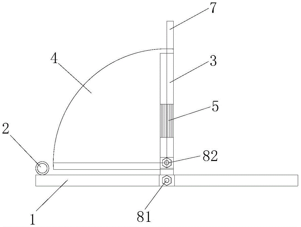
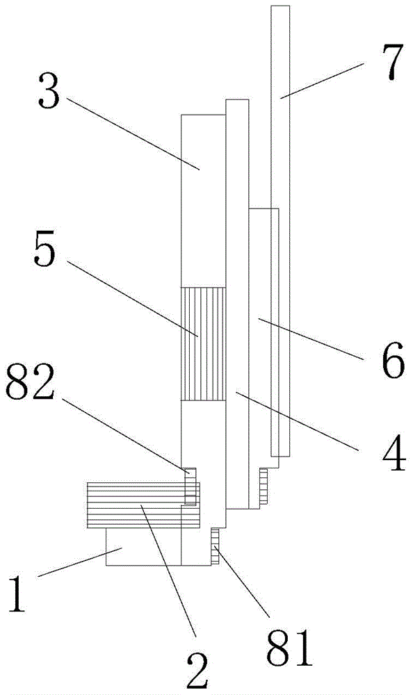
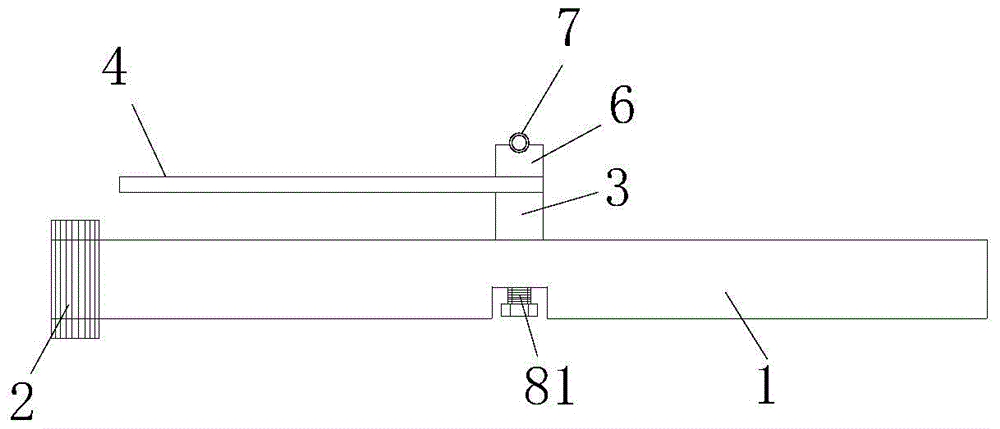
[0031] see Figure 1~3 , This embodiment is provided with a base 1, a base level 2, a protractor level seat 3, a protractor 4, a protractor level 5, an aiming sleeve seat 6 and an aiming sleeve 7.

[0032] The base 1 is a rectangular rod-shaped base. The base level 2 is arranged on the upper surface of the front end of the base 1, the protractor level seat 3 is arranged on the side of the base 1 and is connected to the base 1 through bolts 81 in rotation, the protractor level 4 is arranged in the middle of the protractor level seat 3, the protractor level seat 3, the protractor 4 and The 6 seats of the aiming sleeve seat are connected by bolts 82, the pin shaft 82 passes through the center of the protractor 4, the protractor 4 is located between the protractor level gauge seat 3 and the aiming sleeve seat 6, and the aiming sleeve 7 is embedded in the set point on the aiming sleeve seat. socket (not shown).

[0033] The protractor 4 is a quarter-circle protractor with a scale...

Embodiment 2

[0035] Similar to Embodiment 1, the difference is that the puncture positioner also includes a puncture needle and a puncture needle trocar, and the surface of the puncture needle is provided with a length scale.

[0036] When in use, the puncture needle is inserted into the aiming sleeve and slides along the aiming sleeve, and the puncture needle is used to enter the affected part of the human body for positioning. The puncture needle trocar covers the puncture needle and is slidingly matched with the puncture needle, and the puncture needle trocar is guided into the affected part of the human body through the puncture needle and positioned.

[0037] Provide the clinical use situation of present embodiment 2 below:

[0038] 20 cases of lung puncture biopsy cases with CT positioning were randomly divided into two groups, one group used puncture positioner and anti-rebound device, and the other group used conventional puncture. Both groups were operated by the same operator an...


PUM


Abstract

The invention relates to percutaneous puncturing medical apparatuses and instruments, in particular to a puncturing locator which comprises a base, a base gradienter, an angle gauge gradienter base, an angle gauge, an angle gauge gradienter, a collimation sleeve pipe base and a collimation sleeve pipe. The base gradienter is arranged on the base. The angle gauge gradienter is arranged on the side of the base and is in rotating connection with the base. The angle gauge gradienter is arranged on the angle gauge gradienter base. The angle gauge gradienter base, the angle gauge and a collimation sleeve pipe base connecting piece are connected with each other. The connecting piece penetrates through the circle center of the angle gauge. The angle gauge gradienter base is fixedly connected with the angle gauge. The collimation sleeve pipe base can rotate relative to the angle gauge which is placed between the angle gauge gradienter base and the collimation sleeve pipe base. The collimation sleeve pipe is arranged on the collimation sleeve pipe base. The precision of a horizontal face and a vertical face is controlled through the base gradienter and the angle gauge gradienter of the puncturing locator, the puncturing locator has the advantages of being accurate and reliable in angle locating, the precision of the needle-in angle of an aspiration biopsy needle is guaranteed, and one-time puncturing success rate is obviously improved.

Description

technical field [0001] The invention belongs to medical instruments, and relates to a percutaneous puncture medical instrument, in particular to a puncture positioner. Background technique [0002] Percutaneous biopsy under CT positioning is one of the important methods for diagnosing the nature of deep tumors such as lung, liver, and kidney. However, the ideal puncture angle positioned by CT is often between 0-90 degrees from the horizontal line, that is, the operator must estimate the angle to accurately insert the needle and successfully puncture. For the angle of needle insertion, most clinicians just estimate it with the naked eye, and those who are more careful will use a protractor to make gestures, but there is usually a large deviation. Due to the inaccurate angle of needle insertion, it is often necessary to readjust the angle of needle insertion repeatedly under CT positioning. On the one hand, the success rate of puncture decreases, which increases the pain of p...

Claims


Application Information

Patent Timeline
Patent Type & Authority Patents(China)
IPC IPC(8): A61B90/10A61B10/02
Inventor 杨清杰郭明胡蒙
Owner 杨清杰
Why Eureka
Try Eureka