Fixed stamping deck device

A technology for fixing stamping and decking, applied in positioning devices, feeding devices, storage devices, etc., can solve the problems of easy deviation, unsatisfactory stamping effect, waste of working time, etc., to ensure stamping accuracy and improve production efficiency. Effect

Active Publication Date: 2014-05-28
上海宝山大陆汽车配件有限公司
View PDF5 Cites 1 Cited by
  • Summary
  • Abstract
  • Description
  • Claims
  • Application Information

AI Technical Summary

Problems solved by technology

[0002] The great development of mechanization has promoted the improvement of production efficiency while promoting social progress. In mechanical production, drilling parts is a very common thing. Most of the drilling of thinner parts is directly punched by stamping plates. However, the effect of such stamping is often not ideal, because there is no fixture to clamp the parts
It is easy to cause deviation, and it is a waste of working time to reinstall a fixture

Method used


Image

  • Fixed stamping deck device

Examples


Embodiment Construction

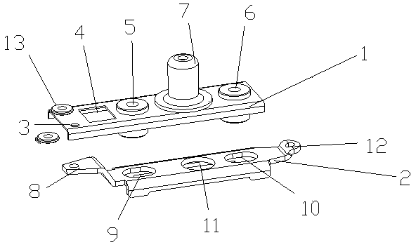
[0010] refer to figure 1 As shown, a fixed stamped deck device includes an upper deck 1 and a lower deck 2, the upper deck 1 is located above the lower deck 2, and a pair of third fixing screw holes 3 and fixing holes 4 are provided on the upper deck 1 , the first fixing buckle 5, the second fixing buckle 6 and the stamping drilling cap 7, the third fixing screw hole 3 is symmetrically arranged on the left end of the upper deck 1, and the fixing hole 4 is arranged on the right side of the third fixing screw hole 3, The first fixing button 5 is arranged on the right side of the fixing hole 4, the second fixing button 5 is arranged on the right side of the first fixing button 5, and the punching drilling cap 7 is arranged on the first fixing button 5 and the second fixing button 6 In the middle position, the lower deck 2 is provided with a movable plate 8, a first fixed buckle screw hole 9, a second fixed buckle screw hole 10, a punched through hole 11 and a handle portion 12, a...


PUM


Abstract

The invention discloses a fixed stamping deck device, comprising an upper deck and a lower deck; the upper deck is positioned above the lower deck; the upper deck is provided with a pair of third bolt fixing holes, a fixing hole, a fixing button, a second fixing button and a stamping drilling cap; a movable plate, a first fixing button threaded hole, a second fixing button threaded hole, a stamping through hole and a handle part are arranged on the lower deck; the movable plate is arranged at the left end of the lower deck; the first fixing button threaded hole is formed in the right end of the movable plate; the stamping through hole is formed in the right end of the first fixing button threaded hole; the handle part is arranged at the right end of the stamping through hole; the second fixing button threaded hole is formed in the position between the stamping through hole and the handle part. As when the fixing stamping deck device can ensure the stamping precision when being used for stamping a part without consuming more time, and the production efficiency is improved.

Description

technical field [0001] The invention relates to a fixed punched deck device. Background technique [0002] The great development of mechanization has promoted the improvement of production efficiency while promoting social progress. In mechanical production, it is a very common thing to drill holes for parts. Most of the holes for thinner parts are directly punched by stamping plates. However, the effect of such stamping is often unsatisfactory, because there is no fixture to clamp the part. It is easy to cause deviation, and it is a waste of working time to reinstall a fixture. Contents of the invention [0003] The technical problem to be solved by the present invention is to realize a fixed stamping deck device. When the device stamps the parts that need to be stamped, there will be no stamping deviation, and at the same time, the working efficiency is high. [0004] In order to solve the above problems, the present invention adopts the following technical solutions:...

Claims


Application Information

Patent Timeline
Patent Type & Authority Applications(China)
IPC IPC(8): B21D43/00
Inventor 胡和萍
Owner 上海宝山大陆汽车配件有限公司
Why Eureka
Try Eureka