High speed air bearing ring

An air flotation and steel ring technology, applied in textiles and papermaking, etc., can solve the problems of yarn breakage, complex structure, and inability to control the rotation speed of the ring ring orbit, reducing friction, reducing mutual rotation, and air pressure. increased effect

Active Publication Date: 2016-05-04
RUGAO CITY DINGYAN TEXTILE
View PDF6 Cites 3 Cited by
  • Summary
  • Abstract
  • Description
  • Claims
  • Application Information

AI Technical Summary

Problems solved by technology

The disadvantage of the magnetic levitation steel ring is that the structure is too complicated to control the rotation speed of the steel ring ring track. When rotating at a low speed, the traveler may rotate with the steel ring ring track. , resulting in yarn breakage

Method used


Image

  • High speed air bearing ring

Examples


Embodiment Construction

[0014] The present invention will be further described below in conjunction with the accompanying drawings and specific embodiments.

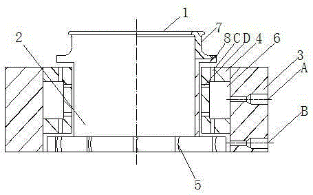
[0015] Such as figure 1 As shown, the high-speed air-floating steel ring of the present invention includes an upper ring ring 1, a lower ring seat 2, an outer ring 3, an inner bushing 4, and a fan blade 5 installed at the bottom of the lower ring seat;

[0016] Such as figure 1 As shown, the inner bushing 4 is in the shape of a ring, the diameter of the outer circle is the same as the diameter of the inner through hole of the outer ring 3, and the height is lower than that of the outer ring 3, and an annular air chamber 6 is arranged on the outer peripheral surface. The bushing 4 is fixedly mounted on the inner side of the outer ring 3, and the upper surfaces of the two are in the same plane; the outer ring 3 is drilled with a plurality of through holes A along the diameter direction in the part opposite to the air chamber 6, and in the part o...


PUM

PropertyMeasurementUnit
diameteraaaaaaaaaa
diameteraaaaaaaaaa

Abstract

A high-speed air flotation steel collar is characterized in that an upper steel collar ring, a lower steel collar seat, an outer circular ring, a neck bush and blades arranged on the lower portion of the lower steel collar seat are included. The high-speed air flotation steel collar has the advantages of being simple in structure, and capable of achieving the function that the upper steel collar ring rotates freely and the rotation speed is controllable.

Description

technical field [0001] The invention relates to a spinning machine part, in particular to a steel ring in the spinning machine part. Background technique [0002] The steel collar of existing ring spinning frame and twisting frame is the key component on the spinning frame, and it cooperates with parts such as steel traveler, spindle, bobbin to jointly complete the twisting and winding of yarn. The existing steel ring is circular, the lower part of the steel ring is a circular base, and the upper part has a circular track. Sliding, the ring is fixed. When working, the yarn is output from the front roller, passes through the traveler after passing through the yarn guide hook, and then is wound on the bobbin. The traveler slides around the circular track at high speed, and the linear speed can reach about 40 m / s. When the traveler clings to the inner runway of the steel ring and slides at high speed, it will generate friction and heat and wear quickly, thus restricting the o...

Claims


Application Information

Patent Timeline
Patent Type & Authority Patents(China)
IPC IPC(8): D01H7/56
Inventor 朱张林
Owner RUGAO CITY DINGYAN TEXTILE
Why Eureka
Try Eureka