Vacuum air-discharging system

A technology of vacuum exhaust and vacuum pump, applied in electrical components, circuits, liquid fuel engines, etc., can solve the problems of vacuum pump stop, reaction by-product mixing, affecting pump limit pressure, etc., to achieve the effect of improving efficiency and prolonging life.

Inactive Publication Date: 2010-11-17
EBARA CORP
View PDF4 Cites 0 Cited by
  • Summary
  • Abstract
  • Description
  • Claims
  • Application Information

AI Technical Summary

Problems solved by technology

[0005] In the existing vacuum exhaust system, a certain amount of shaft seal gas is always introduced regardless of the processing state. However, if a large amount of shaft seal gas is poured in, it will affect the ultimate pressure of the pump at no load, so there is a need to reduce Introduced shaft seal gas volume
However, if the amount of shaft seal gas decreases, there is a problem that by-products of the reaction are mixed into the bearings and lubricating oil of the pump rotor, and the vacuum pump stops.

Method used


Image

  • Vacuum air-discharging system
  • Vacuum air-discharging system
  • Vacuum air-discharging system

Examples


Embodiment Construction

[0027] Refer below Figure 1 to Figure 8 The embodiment of the vacuum exhaust system of the present invention will be described in detail. In addition, in Figure 1 to Figure 8 In the above, the same or equivalent constituent elements are given the same reference numerals to omit overlapping descriptions.

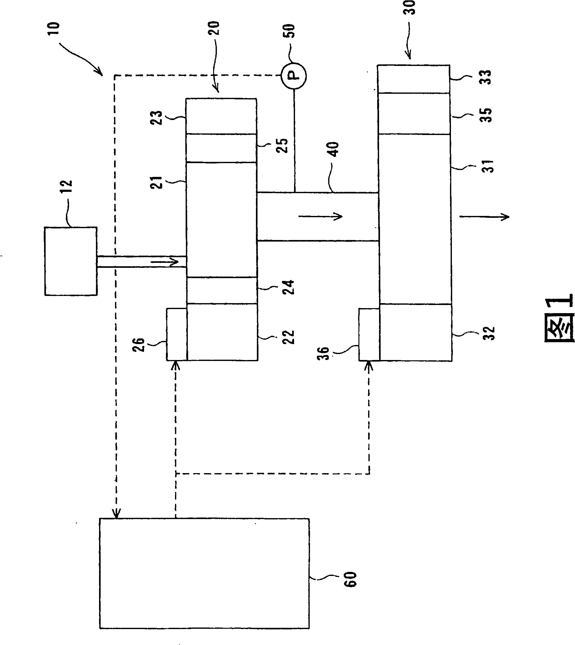
[0028] figure 1 It is a schematic diagram showing the vacuum exhaust system 10 of the first embodiment of the present invention. Such as figure 1 As shown, the vacuum exhaust system 10 is a system for exhausting a vacuum chamber 12 used in a semiconductor manufacturing process or a liquid crystal manufacturing process to a vacuum, and includes: two vacuum pumps 20 and 30; connecting the front vacuum pump 20 and the back stage The connecting pipe 40 of the vacuum pump 30; the pressure sensor 50 that detects the internal pressure of the connecting pipe 40; the control unit 60 that controls the vacuum pumps 20 and 30. The pressure sensor 50 detects the gas pressure in the co...


PUM


Abstract

The invention provides the vacuum-pumping system. The vacuum-pumping system (10) has vacuum pump (20), (30), and pressure sensing device (50). The vacuum pump (20), (30) have two rotors, motor, timing gear, and bootstrap driver (26), (36). The vacuum-pumping system (10) has control section (60), the pressure sensing device (50) detects the pressure, and the bootstrap driver (26), (36) controls the rotating speed of rotors.

Description

technical field [0001] The present invention relates to a vacuum exhaust system, and in particular to a vacuum exhaust system for exhausting a vacuum chamber into a vacuum used in a semiconductor manufacturing process or a liquid crystal manufacturing process. Background technique [0002] Conventionally, in a semiconductor manufacturing process, a liquid crystal manufacturing process, etc., a vacuum evacuation system for evacuating a vacuum chamber to a vacuum is used. In this vacuum evacuation system, the vacuum pump operates at a rated value irrespective of the conditions of the semiconductor manufacturing process, the liquid crystal manufacturing process, and the like. However, after the rated operation of the vacuum pump is continued regardless of the processing state, the load on the vacuum pump increases as the amount of gas delivered by the vacuum pump (gas load) increases. Therefore, there is a problem that the efficiency of the vacuum exhaust system is lowered, an...

Claims


Application Information

Patent Timeline
Patent Type & Authority Patents(China)
IPC IPC(8): F04D27/00F04C28/00F04B49/00
CPCF04B37/14F04C25/02F04C29/0092F04D9/048H01L21/02
Inventor 田中敬二杉浦哲郎香川浩一
Owner EBARA CORP
Why Eureka
Try Eureka