Connector device and connector used therein

A technology for connectors and moving parts, which is applied to parts of connecting devices, devices for connecting/disconnecting connecting parts, connections, etc., can solve the problem of not having to display the fitting state between connectors and so on.

Active Publication Date: 2014-05-28
HIROSE ELECTRIC GROUP
View PDF2 Cites 2 Cited by
  • Summary
  • Abstract
  • Description
  • Claims
  • Application Information

AI Technical Summary

Problems solved by technology

However, this connector device does not have the function of displaying the mating state of the connectors

Method used


Image

  • Connector device and connector used therein
  • Connector device and connector used therein
  • Connector device and connector used therein

Examples


Embodiment Construction

[0071] A preferred embodiment of the present invention will be described with reference to the accompanying drawings.

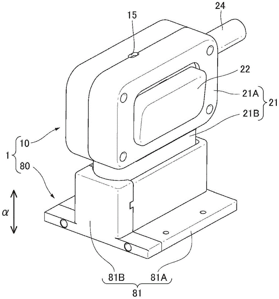
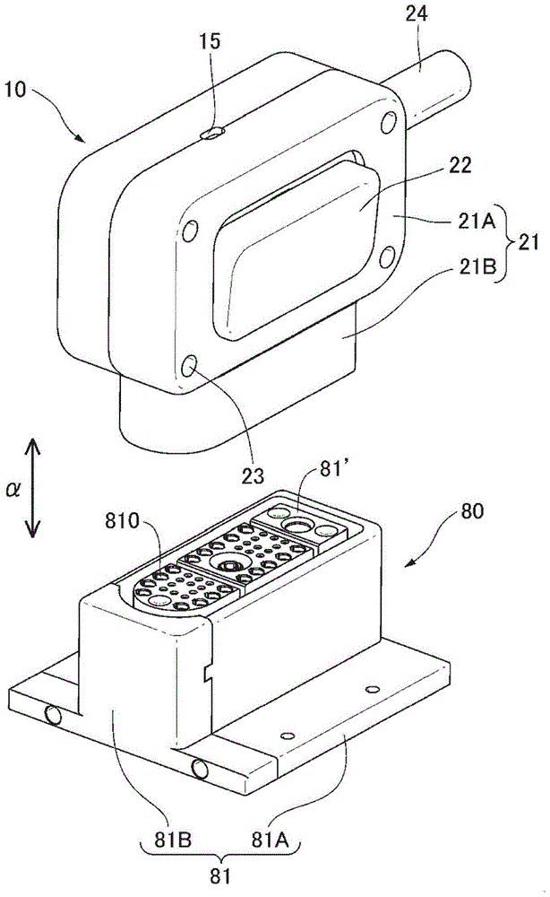
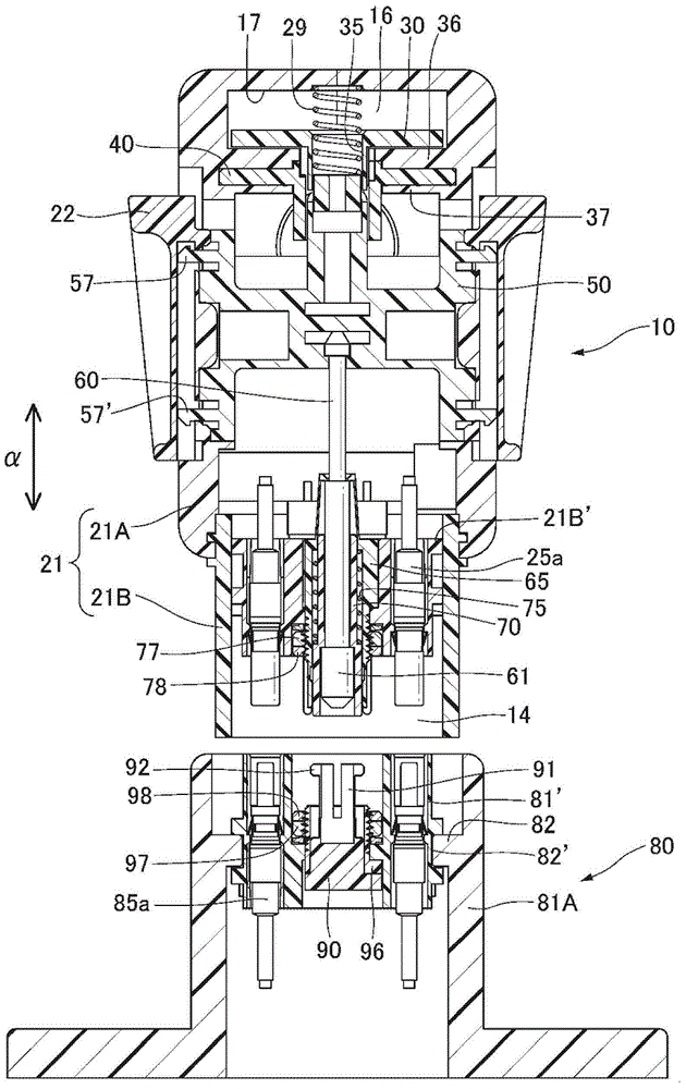
[0072] figure 1 , figure 2 A perspective view showing a connector device 1 of a preferred example of the present invention. The present connector device 1 is composed of a cable connector 10 and a board connector 80 which form a pair and can be fitted with each other. figure 1 Indicates the state after these cable connectors 10 are fitted with the board connector 80, figure 2 Indicates their state before chimerism. In addition, these cable connectors 10 and board connectors 80 both have almost bilaterally symmetrical shapes.

[0073] The cable connector 10 includes at least: an upper housing 21A and a lower housing 21B that can be fixed to each other; and sliders 22 (22') respectively provided on left and right outer surfaces of the upper housing 21A. The slider 22 (22') is provided in a movable state with respect to the upper case 21A and the lower ...


PUM


Abstract

A connector device and a connector uses therein can mechanically display a fit state of the connector according to fit operation. The connector device is composed of a first connector and a second connector which can be fitted with each other. The first connector includes a connector housing, a movable component which is disposed in the connector housing, extended toward a fitting side of the first connector and the second connector, and is movable in the first connector through the effect from the second connector when the first connector and the second connector are fitted or in at least one of the two connectors when the fitting of the first connector and the second connector is released, and a confirmation component which, when the movable component acts in the first connector, can change a confirmation state of that confirmation is conducted form the outside of the connector housing through the action of the movable component.

Description

technical field [0001] The present invention relates to a connector device composed of a pair of first connector and second connector capable of mating with each other, and in more detail, displays the fitting state of the first connector and the second connector when they are mated. The connector device and the connector it uses. Background technique [0002] As such a conventional connector device, there is, for example, a connector device disclosed in JP-A-6-13069. Figure 22 A connector device disclosed in this publication is shown. This connector device is constituted by a male housing 105 and a female housing 106 forming a pair. [0003] After these male housings (connectors) 105 and female housings 106 face each other, they are fitted together so that the male housings 105 are inserted into the openings 161 of the female housings 106 . At this time, the guide protrusions 152a, 153a of the male housing 105 fit into the guide grooves 163a, 164a of the female housing 1...

Claims


Application Information

Patent Timeline
Patent Type & Authority Applications(China)
IPC IPC(8): H01R13/62
CPCH01R13/639H01R13/6392H01R13/6395H01R13/6397H01R13/641H01R13/6463H01R13/6464
Inventor 土田雅裕尾崎哲也
Owner HIROSE ELECTRIC GROUP
Why Eureka
Try Eureka