Supercharge Your Innovation With Domain-Expert AI Agents!

Fuel tank cap lock

A storage tank cover and equipment technology, applied in mechanical equipment, building locks, vehicle locks, etc., can solve the problems of high assembly cost, complex structure, and easy interference.

Active Publication Date: 2014-05-28
KIEKERT AG
View PDF6 Cites 12 Cited by
  • Summary
  • Abstract
  • Description
  • Claims
  • Application Information

AI Technical Summary

Problems solved by technology

In this case, the previously used mechanisms are structurally very complex and have multiple components
As a result, a stronger drive is required for the closing process, which is usually controlled by a central locking device
Multiple structurally complex parts also lead to high assembly costs and susceptibility to interference

Method used


Image

  • Fuel tank cap lock
  • Fuel tank cap lock
  • Fuel tank cap lock

Examples


Embodiment Construction

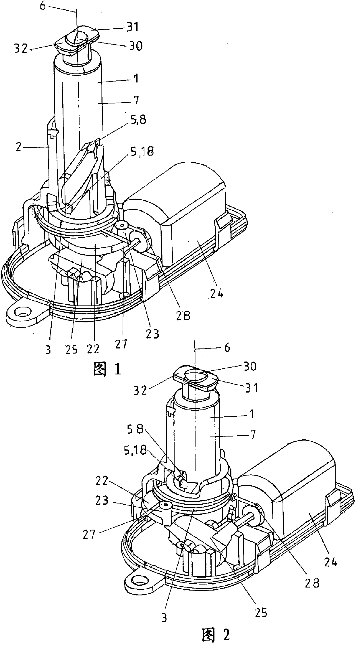
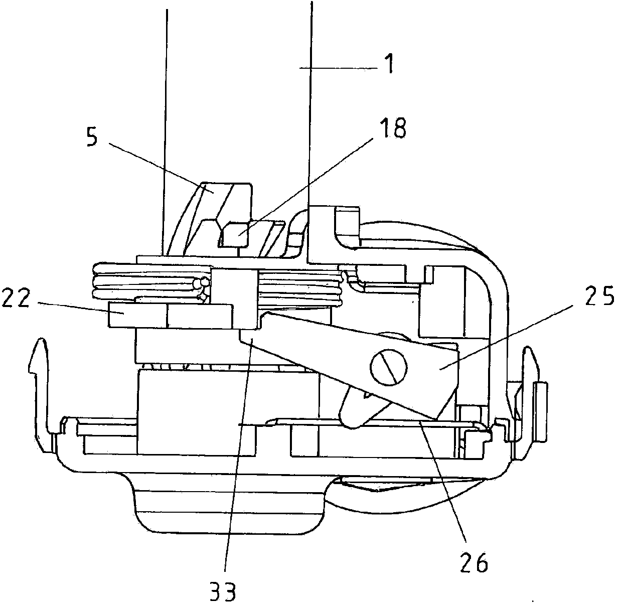
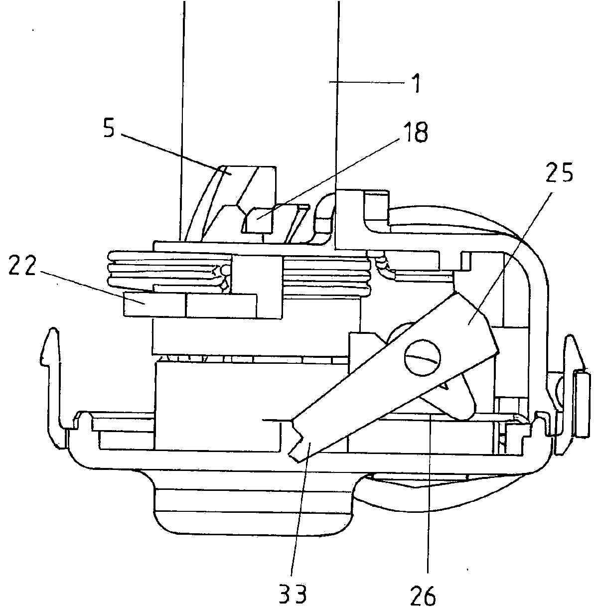
[0045] figure 1 A view of the interior of the lock device is shown with the locking pin 1 in the open position. In order to make the illustration more intuitive, only a part of the housing 2 is shown which is marked with the corresponding reference number. On its peripheral surface 7 the locking pin 1 has a sliding guide 5 which, in cooperation with the pin 18 , serves as a positive guide 8 between the locking pin 1 and the housing 2 . Functionally supplementary, a torsion spring 3 is provided which surrounds the locking pin 1 in the region of the pivot lever 22 . The reference number 24 designates a drive in the form of a motor for the locking pawl 25, by means of which the locking pin 1—more precisely the rocker 22—is fixed in the locked position so that it cannot be locked otherwise. to operate. The two legs 27 , 28 serve to support the torsion spring 3 in order to build up a preload on the rocker 22 in relation to the stop 23 . A possible emergency unlocking device is ...


PUM


Abstract

The invention relates to a lock for a fuel tank or tailgate in a vehicle, comprising a locking bolt (1) which can be adjusted between an open and closed position by opening and closing the cap or the tailgate. Said cap lock, in the housing (2) of the locking device, is positively driven counter to the force of a compression spring (4) in the direction of its longitudinal axis (6) and counter to the force of a torsion spring (3) about its longitudinal axis (6).

Description

technical field [0001] The invention relates to a lock device for a tank lid / fuel tank lid or charging lid in a vehicle, having a locking pin movable between an open position and a closed position by opening and closing the tank lid or charging lid . Background technique [0002] For example DE 10 2011 076 810 discloses a locking device for a tank lid. The tank lid is closed manually at the end of the tank operating process, wherein force is applied to the latch to move the latch from its out-of-out open position to its in-in closed position. When the tank cover is actuated, the (lock) pin is simultaneously rotated about its longitudinal axis and is thus fixed in the tank cover at its end facing the tank cover, so that a latch is produced. In this case, the previously used mechanisms are structurally very complex and have multiple components. As a result, a stronger drive is also required for the closing process, which is normally controlled by a central locking device. ...

Claims


Application Information

Patent Timeline
IPC IPC(8): E05B83/28E05B83/34E05B85/00
CPCB60K2015/053E05C19/022B60K15/05E05B83/34B60K2015/0546B60K2015/0584B60K2015/0576B60Y2400/90Y10T292/0864Y10T292/0868Y10T292/101Y10T292/1005Y10T292/54Y10T292/0834Y10T292/0837Y10T292/084Y10T292/096Y10T292/1013Y10T292/1016Y10T292/1014E05C19/02E05C19/06E05C19/16E05C19/028E05C19/165B60K2015/0515B60K2015/0561
Inventor M·S·巴萨瓦拉加帕H·瓦曼
Owner KIEKERT AG
Features
  • R&D
  • Intellectual Property
  • Life Sciences
  • Materials
  • Tech Scout
  • Unparalleled Data Quality
  • Higher Quality Content
  • 60% Fewer Hallucinations
Learn More