Near-infrared cut-off filter

A cut-off filter and near-infrared technology, which is applied in the direction of instruments, optics, optical components, etc., can solve the problems of small refractive index difference, inability to fully form a stop band, and inability to fully suppress the incidence angle dependence, etc., to achieve the incidence angle dependence inhibitory effect

Active Publication Date: 2014-05-28
ASAHI GLASS CO LTD
View PDF9 Cites 19 Cited by
  • Summary
  • Abstract
  • Description
  • Claims
  • Application Information

AI Technical Summary

Problems solved by technology

[0009] Regarding the method of increasing the refractive index of the low refractive index film, if the refractive index is not increased extremely, the incident angle dependence cannot be sufficiently suppressed, and if the refractive index of the low refractive index film is increased excessively, the high refractive index film and the The refractive index difference of the low-refractive index film becomes too small, and the transmission band becomes too wide. On the other hand, the transmittance reduction of the stop band is insufficient and becomes very narrow, and the stop band on the ultraviolet region side cannot be suffic

Method used


Image

  • Near-infrared cut-off filter
  • Near-infrared cut-off filter
  • Near-infrared cut-off filter

Examples


Embodiment

[0168] Hereinafter, it demonstrates more concretely with reference to an Example.

[0169] Examples 1 to 4 are examples of the near-infrared cut filter of the present invention. In addition, Examples 5 to 14 are examples in which the spectral transmittance at each incident angle was calculated by optical simulation for the laminated film of each structure.

example 1

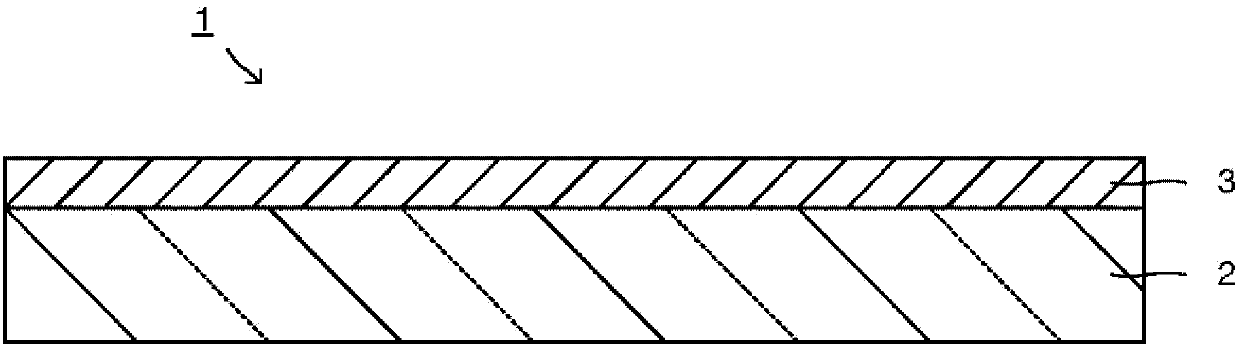
[0171] The near-infrared cut filter has a structure in which one main surface of the transparent substrate has a transmission band forming portion which is a part of the optical multilayer film, and has a stop band forming portion which is a part of the optical multilayer film on the other main surface. Here, the transparent substrate is colorless transparent glass (manufactured by SCHOTT, trade name: D263, thickness: 0.3 mm), or near-infrared cut glass (manufactured by Asahi Glass Co., Ltd., trade name: NF- 50T, thickness: 0.26mm).

[0172] The transmissive zone constituting part used the transmissive zone constituting part having the structure shown in Table 1 in the first form. The number of layers in the table is the number of layers from the transparent substrate side. Here, in the TiO that will be used as a high refractive index film 2 The film is denoted as H, and Ta as the middle refractive index film 2 o 5 The film is denoted as M, and SiO as a low refractive inde...

example 2

[0189] The near-infrared cut filter has a configuration in which a transmission band constituting part of the optical multilayer film is formed on one main surface of a transparent substrate, and a stop band constituting part of the optical multilayer film is formed on the other main surface. Here, the transparent substrate and the barrier band constituting portion are the same as in Example 1.

[0190] The transmissive zone constituting part used the transmissive zone constituting part of the second embodiment having the structure shown in Table 6. FIG. Here, in the TiO that will be used as a high refractive index film 2 The film is denoted as H, and Ta as the middle refractive index film 2 o 5 When the film is denoted as M, the transmission band constituting part is basically constituted by the basic unit of [HM]. In addition, the number of layers is 52 layers, TiO 2 The average optical film thickness T of the film H 210.7nm, Ta 2 o 5 The average optical film thicknes...


PUM


Abstract

Provided is a near-infrared cut-off filter with which angle of incidence dependency is alleviated and the visible light transmission band is expanded, as are the ultraviolet and near-infrared region rejection bands. The near-infrared cut-off filter comprises: a transparent substrate; and an optical multilayer film which is disposed upon at least one primary face of the transparent substrate, further comprising two or more types of films with different refractions of 2.0 or more, and a film with a refraction of 1.70 or less. With respect to spectrum characteristics in perpendicular entry conditions, the optical multilayer film further has a transmission region with an average transmission rate of 85% or more in the 400-700nm wavelength range, and rejection bands in the ultraviolet side and the near-infrared side with respective average transmission rates of 5% or less. The optical multilayer film has a transmission band configuration part for forming the transmission band, and a rejection band configuration part for forming the rejection band.

Description

technical field [0001] The present invention relates to a near-infrared cut filter, in particular to a near-infrared cut filter with an optical multilayer film on a transparent substrate. Background technique [0002] The spectral sensitivity of solid-state imaging devices such as CCD and CMOS used in digital cameras and video cameras has a strong sensitivity to near-infrared light compared to the photosensitivity characteristics of humans, so spectral correction must be performed using a near-infrared cut filter. Conventionally, as near-infrared cut filters, for example, Cu-containing 2+ Near-infrared-absorbing colored glass filters, such as fluorophosphate-based glasses with ions as the coloring component, cannot sufficiently cut off light in the near-infrared and ultraviolet regions when used alone. Optical multilayer film. [0003] In this case, for example, the half-value wavelength on the ultraviolet side of the transmission band that transmits visible light is deter...

Claims


Application Information

Patent Timeline
IPC IPC(8): G02B5/28B32B7/02
CPCG02B5/282
Inventor 馆村满幸
Owner ASAHI GLASS CO LTD
Why Eureka
Try Eureka