Near Infrared Cut Filter

A cut-off filter, near-infrared technology, applied in instruments, optical components, optics, etc., to achieve the effect of suppressing the dependence of the incident angle

Active Publication Date: 2017-07-11
ASAHI GLASS CO LTD
View PDF3 Cites 0 Cited by
  • Summary
  • Abstract
  • Description
  • Claims
  • Application Information

AI Technical Summary

Problems solved by technology

Along with this, the incident angle dependence of the wavelength region cut off by the optical multilayer film becomes a problem

Method used


Image

  • Near Infrared Cut Filter
  • Near Infrared Cut Filter
  • Near Infrared Cut Filter

Examples


Embodiment approach

[0044] Hereinafter, the near-infrared cut filter of the present invention will be described with reference to the drawings.

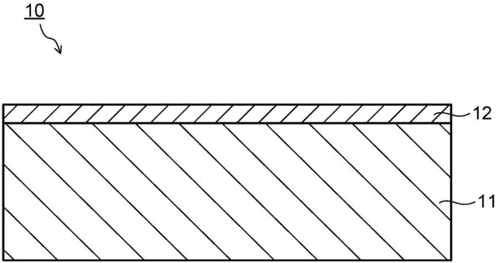
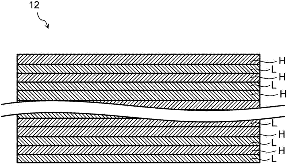
[0045] figure 1 It is a cross-sectional configuration diagram of the near-infrared cut filter 10 (hereinafter, IRCF10 ) according to the embodiment. Such as figure 1 As shown, the IRCF 10 includes a transparent substrate 11 and an optical multilayer film 12 provided on at least one main surface of the transparent substrate 11 . It should be noted that the optical multilayer film 12 may be provided on one main surface of the transparent substrate 11 , or may be separately provided on each main surface of the transparent substrate 11 .

[0046] (transparent substrate 11)

[0047] The material of the transparent substrate 11 is not particularly limited as long as it can transmit at least light in the visible wavelength region. As the material of the transparent substrate 11, for example, crystals such as glass, crystal, lithium niobate, and sapphire; p...

Embodiment 1~4

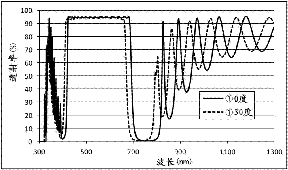
[0149] First, Examples 1 to 4 will be described. In Examples 1-4, titanium oxide (TiO 2 ) As the material of the high refractive index film, silicon oxide (SiO 2 ) as the material of the low refractive index film. It should be noted that titanium oxide (TiO 2 ) has a refractive index of 2.47 at a wavelength of 500nm, making silicon oxide (SiO 2 ) has a refractive index of 1.48 at a wavelength of 500nm, simulating spectral characteristics. Hereinafter, the film conditions of Examples 1 to 4 are shown in Tables 1 to 4, and the simulation results of Examples 1 to 4 are shown in Tables 1 to 4. Figure 6-9 . In addition, the "film thickness" in Tables 1-4 is a physical film thickness. In addition, the "value of the coefficient" is a coefficient indicating how many times the physical film thickness is QWOT.

Embodiment 1

[0151] [Table 1]

[0152] layers membrane material Film thickness d[nm] The value of the coefficient layers membrane material Film thickness d[nm] The value of the coefficient 1 TiO 2

106.18 2.0981168 28 SiO 2

46.10 0.5458240 2 SiO 2

83.64 0.9902976 29 TiO 2

100.77 1.9912152 3 TiO 2

12.68 0.2505568 30 SiO 2

27.77 0.3287968 4 SiO 2

41.87 0.4957408 31 TiO 2

15.92 0.3145792 5 TiO 2

77.08 1.5231008 32 SiO 2

43.47 0.5146848 6 SiO 2

42.00 0.4972800 33 TiO 2

100.99 1.9955624 7 TiO 2

22.14 0.4374864 34 SiO 2

31.26 0.3701184 8 SiO 2

43.76 0.5181184 35 TiO 2

15.13 0.2989688 9 TiO 2

79.74 1.5756624 36 SiO 2

41.80 0.4949120 10 SiO 2

33.03 0.3910752 37 TiO 2

100.29 1.9817304 11 TiO 2

24.18 0.4777968 38 SiO 2

32.90 0.3895360 12 SiO 2

...


PUM


Abstract

The near-infrared cut filter according to the present invention includes a transparent substrate and an optical multilayer film provided on at least one main surface of the transparent substrate, wherein the optical multilayer film has a high refractive index having a refractive index of 2.0 or more at a wavelength of 500 nm. film and a low refractive index film below 1.6, and the QWOT of the high refractive index film at a wavelength of 500nm is Q H , Set the QWOT at the wavelength of 500nm of the low-refractive index film as Q L When , the optical multilayer film has (a n Q H , b n Q L 、c n Q H 、d n Q L )^n repeating structure, a n The average value is 1.5 ~ 2.5, the b n 、c n 、d n The value obtained by averaging each average value is 1.0 or less.

Description

technical field [0001] The present invention relates to a near-infrared cut filter, and more particularly to a near-infrared cut filter having an optical multilayer film formed on a transparent substrate. Background technique [0002] CCD (Charge Coupled Device: Charge Coupled Device) image sensors, CMOS (Complementary Metal Oxide Semiconductor: Complementary Metal Oxide Semiconductor) image sensors, etc. (hereinafter referred to as solid-state imaging elements) are used in digital cameras, digital video cameras, and the like. However, the spectral characteristics of these solid-state imaging devices are more sensitive to infrared light than human visibility characteristics. Therefore, digital cameras, digital video cameras, and the like perform spectrum correction using near-infrared cut filters. [0003] As a near-infrared cut filter, for example, Cu 2+ Near-infrared-absorbing colored glass filters such as fluorophosphoric acid-based glass with ions as the coloring compo...

Claims


Application Information

Patent Timeline
Patent Type & Authority Patents(China)
IPC IPC(8): G02B5/28
CPCG02B5/282G02B5/208G02B5/283
Inventor 馆村满幸
Owner ASAHI GLASS CO LTD
Why Eureka
Try Eureka