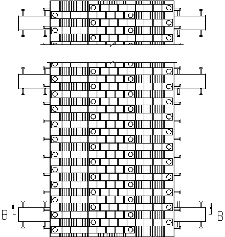
Rack type bridge expansion device
An expansion device and rack-type technology, applied in the field of bridge expansion joints, to achieve low cost, comfortable vehicle operation, and strong ability to adapt to three-dimensional deformation of bridges
- Summary
- Abstract
- Description
- Claims
- Application Information
AI Technical Summary
Problems solved by technology
Method used
Image
Examples
Embodiment
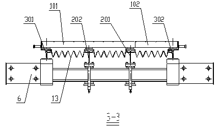
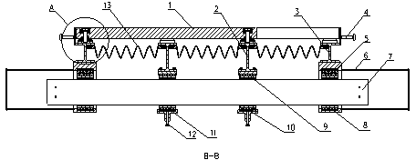
[0046] Such as Figure 1-5 As shown, a rack-type bridge telescopic device includes rack 1, H-shaped middle beam 2, H-shaped side beam 3, displacement box 6, beam 7, compression spring I5, support I8, compression spring II10, support II9, Sliding frame 11, waterproof rubber strip 13 and bolt 18; Its concrete structure is as follows:
[0047] The displacement box 6 is anchored to the beam end of the bridge through concrete pouring, and plays the role of fixing the expansion device and being connected to the expansion joint of the bridge.
[0048] The inner cavity of the displacement box 6 is provided with a compression spring I5 and a support I8, and the two ends of the beam 7 are pre-pressed in the displacement box 6 through the compression spring I5 and the support I8; the H-shaped side beam 3 and the displacement box 6 are fixed as a whole ; In this way, the H-shaped side beam 3 can be fixed to prevent it from slipping.
[0049] The inner cavity of the sliding frame 11 is p...
PUM
 Abstract
Description
Claims
Application Information
 - R&D
- Intellectual Property
- Life Sciences
- Materials
- Tech Scout
- Unparalleled Data Quality
- Higher Quality Content
- 60% Fewer Hallucinations
Browse by: Latest US Patents, China's latest patents, Technical Efficacy Thesaurus, Application Domain, Technology Topic, Popular Technical Reports.
© 2025 PatSnap. All rights reserved.Legal|Privacy policy|Modern Slavery Act Transparency Statement|Sitemap|About US| Contact US: help@patsnap.com


