Head-body separation device with guide function

A separation device and guidance technology, applied in the direction of projectiles, self-propelled bombs, offensive equipment, etc., can solve the problems of reducing the launch range of the carrier, increasing the structural quality of the aircraft and the separation body, and not being able to meet the separation requirements of the long-range aircraft. , to achieve the effect of solving the problem of separation protection, light weight and reliable separation

Inactive Publication Date: 2011-03-30
THE GENERAL DESIGNING INST OF HUBEI SPACE TECH ACAD
View PDF5 Cites 13 Cited by
  • Summary
  • Abstract
  • Description
  • Claims
  • Application Information

AI Technical Summary

Problems solved by technology

The separate design of two sets of mechanisms (separation mechanism and guide mechanism) inevitably increases the structural quality of the aircraft and the separation body, reduces the range of the carrier, and cannot meet the head-to-body separation requirements of long-range aircraft

Method used


Image

  • Head-body separation device with guide function
  • Head-body separation device with guide function
  • Head-body separation device with guide function

Examples


Embodiment Construction

[0013] Below in conjunction with accompanying drawing and example the present invention is described in further detail.

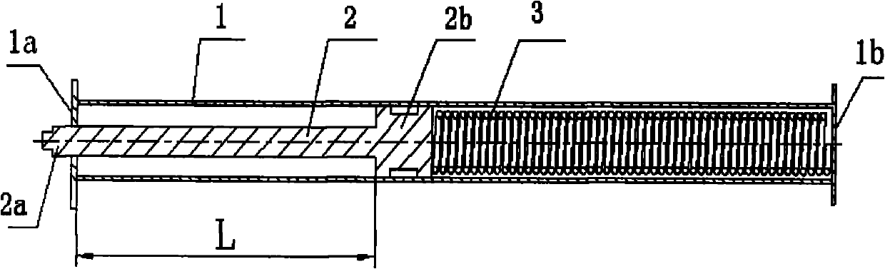
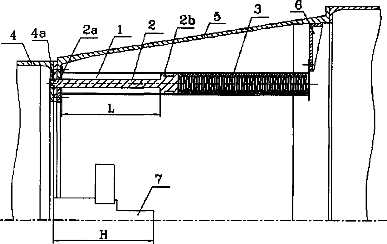
[0014] Such as figure 1 As shown, the head-body separation device with guiding function of the present invention includes a guide assembly and a thrust assembly, the guide assembly and the thrust assembly are installed in the cylinder body 1, and the guide push rod 2 and the thrust spring 3 are installed in the cylinder body 1; The front end 2a of rod 2 stretches out the front cover 1a of cylinder block 1, as the thrust end that pushes against the head, that is, the rear end of aircraft 4, the rear end of guide push rod 2 is the piston 2b matched with the inner diameter of cylinder block 1, between piston 2b and cylinder A compression spring 3 is placed in the cylinder cavity between the rear covers 1b of the body 1, and the rear cover 1b of the cylinder 1 is fixed on the separating body 5 through a base 6.

[0015] Further, the maximum stroke L of the gui...


PUM


Abstract

The invention provides a head-body separation device with a guide function, comprising a guide assembly and a thrust assembly, wherein the guide assembly and the thrust assembly are arranged in a cylinder body and respectively comprise a guide push rod and a thrust spring which are arranged in the cylinder body; the front end of the guide push rod extends out of a front cover of the cylinder bodyand is used as a thrust end pushing against the head, namely the rear end of an aircraft, a piston which is matched with the inner diameter of the cylinder body is arranged at the rear end of the guide push rod, a compression spring which is arranged in a cylinder body chamber is arranged between the piston and a rear cover of the cylinder body, and the rear cover of the cylinder is fixed on the inner wall of a separation body through a base. The maximum stroke L of the guide push rod is smaller than the maximum compression amount 5mm-10mm of the spring. The maximum stroke L of the guide pushrod is greater than the maximum length H about 5mm-10mm of a protruding structure on the rear end surface of the aircraft. The front end of the guide push rod is sunk in a groove at the rear end of the aircraft.

Description

technical field [0001] The invention relates to a head-body separation device with a guiding function, in particular to a head-body separation device with protrusions on the rear end surface of an aircraft, belonging to the technical field of head-body separation structures, and specifically a head-body separation device with integrated separation and guidance functions device. Background technique [0002] In order to transport the aircraft to the predetermined airspace, the launch vehicle usually uses a multi-stage engine connected in series. After the rocket is separated step by step and reaches the predetermined airspace, the aircraft and the carrier are separated from the head and body. In order to reduce the quality of the aircraft and increase the firing range, usually some structural parts and the attitude control engine of the aircraft are stretched into the separation body (installed on the rear end face of the aircraft). In order to reduce the impact of the sepa...

Claims


Application Information

Patent Timeline
Patent Type & Authority Applications(China)
IPC IPC(8): F42B15/36
Inventor 梁纪秋范开春郑菊鲍永定
Owner THE GENERAL DESIGNING INST OF HUBEI SPACE TECH ACAD
Why Eureka
Try Eureka