Tubular valve device

a valve device and tube valve technology, applied in the field of valves, can solve the problems of correspondingly large and power-demanding magnetic drives, difficult to achieve self-closing functions, etc., and achieve the effects of simple and power-saving, simple and fast valve closure, and simple opening and closing

Inactive Publication Date: 2012-10-16
KARL DUNGS
View PDF22 Cites 12 Cited by
  • Summary
  • Abstract
  • Description
  • Claims
  • Application Information

AI Technical Summary

Benefits of technology

[0008]Such a valve permits the shifting of the valve seat rings by means of the adjustment arrangement of the valve closure member. The adjustment arrangement of the valve closure member can be used in a targeted manner to shift the valve seat rings into a locking position in which they can be held in place by the locking arrangement. Once the valve seat rings have been locked in this position, the valve closure member can be moved away from the valve seat rings by actuating the adjustment arrangement in order to permit the gas flow, or the flow of another fluid, in a controlled manner. In so doing, the valve closure member can be used for a fine adjustment of the fluid flow, as well as for simple opening and closing. Preferably, the adjustment arrangement is configured in such a manner that the adjustment speed of the valve closure member, as well as its positioning, can be controlled in a finely adjusted manner. For example, a stepper motor drive may be used for the adjustment of the valve closure member.
[0011]The return spring acts on the valve seat ring. The applied gas pressure generates only a minimal force acting on the valve seat ring. The effective surface that is affected by the gas pressure is merely the face of the valve seat ring. This prevents shock-like closure operations, on account of which the fluid medium flowing through the valve causes the valve closure member and the valve seat to impact hard against each other due to static pressure or due to additionally occurring dynamic pressure. This reduces wear on the valve seat and on the valve closure member.
[0012]In addition, the concept in accordance with the invention permits, without problems, the combination of the fine adjustment function of a valve comprising a valve closure member that can be finely positioned with the rapid closure function of an open / close valve. This is achieved in that the rapid closure function is associated with the valve seat ring, whereas the fine adjustment function is associated with the valve closure member.
[0014]The aforementioned advantages can also be achieved with the valve having a single valve seat ring and a locking device in the valve configured as a magnetic coil or, if required, also in another manner, said magnetic coil being arranged inside or outside the tubular housing. The arrangement of the magnetic coil locks at least one valve seat ring in the housing. The magnetic coil may be cooled by the fluid stream flowing through the housing. This measure allows higher current densities in the magnetic coil and thus save copper.
[0017]The valve in accordance with the invention permits the use of particularly energy-saving drives. In addition, this results in a high volume flow with a small nominal width and an overall small construction volume. On its ends, the tubular housing may be provided with threads, flanges or other connecting means. In addition, at least when the valve closure member is associated with two valve seat rings, a tightness check can be performed. This applies, in particular, when the two valve seat rings are sealed relative to each other in order to define a central space included between the valve seat rings, to which central space a pressure monitor can be attached. Furthermore, it has been found that the valve concept results in valves that can function independently of their built-in position. Furthermore, the concept is suitable for a pressure range between 0 and several bar and thus for many applications for many different customers. The valve can be actuated quietly. Opening and closing noise is minimized. As mentioned, the fluid flow can be continuously modulated. Furthermore, said concept is based on few components and can be easily adapted to various situations of use.

Problems solved by technology

Frequently, this results in relatively large and correspondingly power-demanding magnetic drives.
Considering such valves, it is relatively difficult to achieve a self-closing function that is required when the valve closes automatically in case of danger.
The correspondingly heavily dimensioned return springs can result in a shock-like, hard placement of the valve closure member on the valve seat and, in the course of time, cause damage there.

Method used


Image

  • Tubular valve device
  • Tubular valve device
  • Tubular valve device

Examples


Embodiment Construction

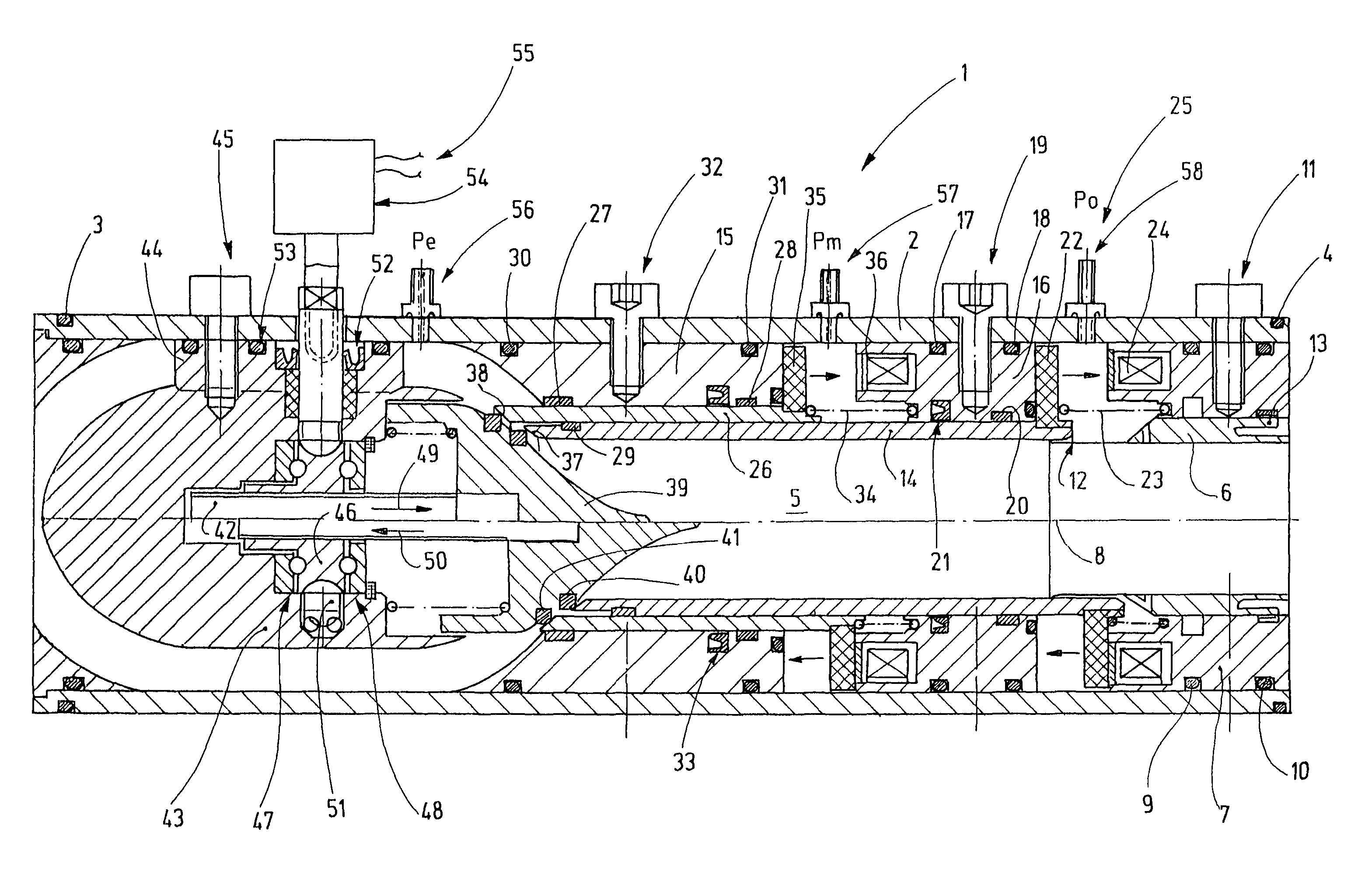
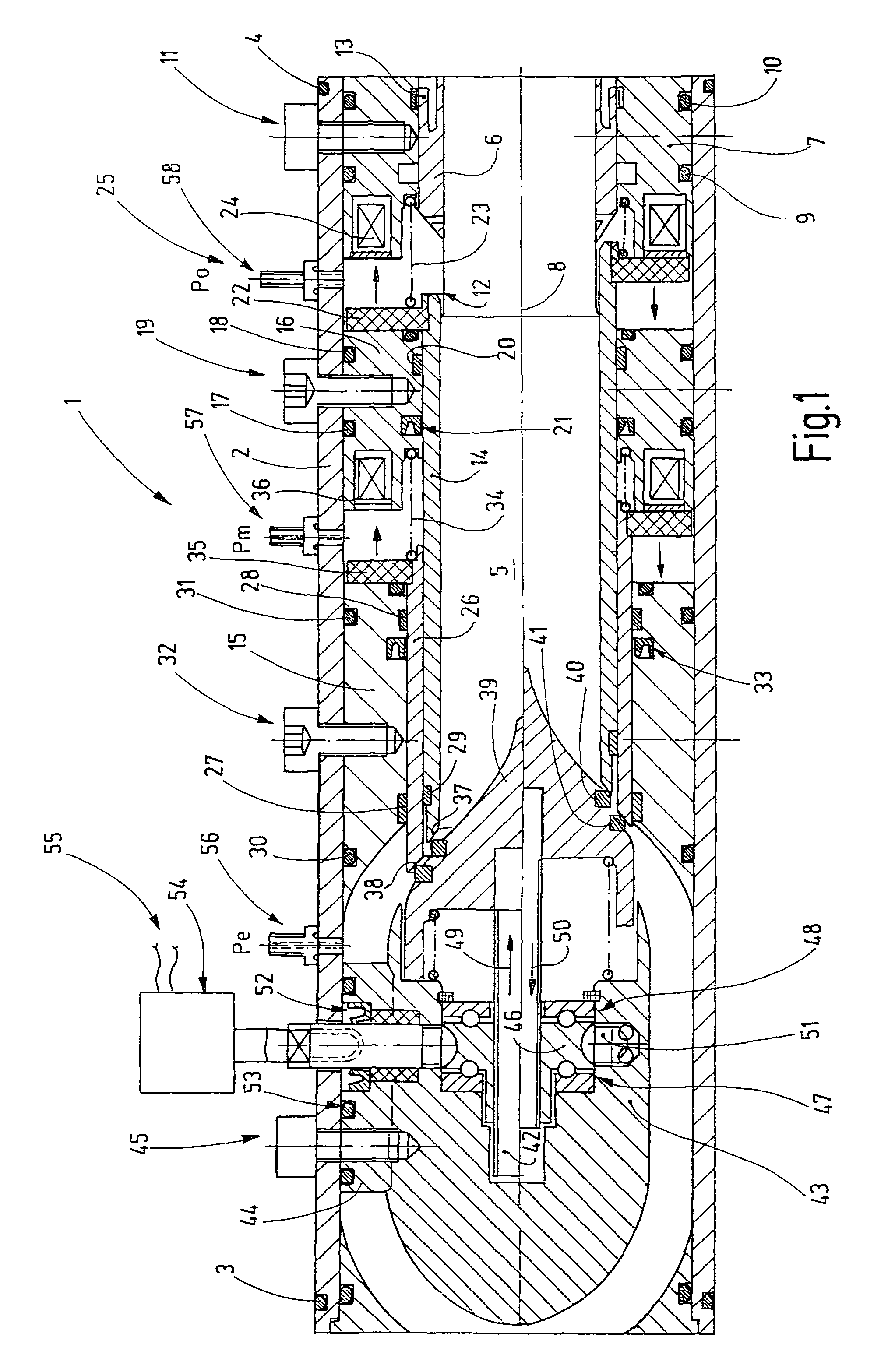
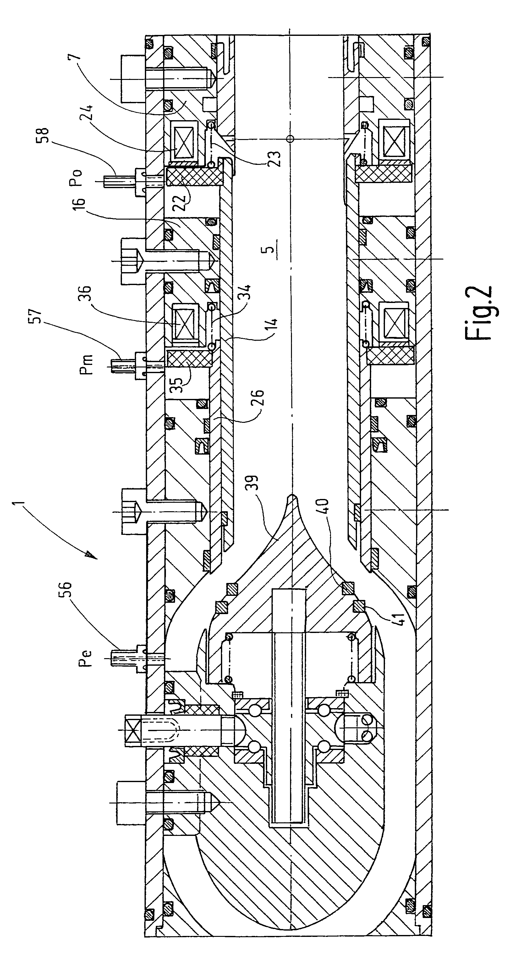
[0021]FIG. 1 shows a valve 1 that has a tubular housing 2, for example, a gas valve that is disposed to act as a gas safety valve, for example. On its two ends that face away from each other, the housing 2 is provided with not specifically illustrated connecting means for the connection of additional pipes and, for example, seals 3, 4. Inside the housing 2, a fluid channel 5 is defined, said channel leading from one end to the other end. On its input side, the fluid channel 5 is delimited by a tubular guide piece 6 that is stationarily held by a ring 7 in the housing and is concentric to a center axis 8. The ring 7 has on its preferably cylindrical outside circumference at least one or also more circumferential grooves in which seals 9, 10 may be placed in order to seal the ring 7 in axial direction against the inside wall of the tubular housing 2. A screw 11 may be provided to secure the ring 7 in place.

[0022]The insert 6 has a tubular lip 12 that extends away from the open end of ...


PUM


Abstract

The presented valve (1) is based on two axially adjustable sleeve-shaped valve seat rings (14, 36) that are associated with locking arrangements in the form of annular armature plates (22, 35) and associate holding coils (24, 36). The valve closure member (39) can be variably adjusted via a position adjustment drive. Said valve closure member has a double function. On the one hand, it acts to move the valve seat rings (14, 26) into locking position and, on the other hand, it acts to control the gas flow.

Description

BACKGROUND OF THE INVENTION[0001]The invention relates to a valve in the form of a pipe as well as to a method for releasing and blocking a fluid stream by means of such a valve.[0002]Basically, valves have a valve housing and, arranged therein, at least one valve closure member. Frequently, the valve closure member can be moved relative to a valve seat in a linear back-and-forth manner in order to close and open the valve seat in a controlled manner. Frequently, to actuate such valves, pull-type electromagnets are used whose armature moves the valve closure member against the force of a return spring away from the valve seat. Such magnets have a self-closing function. When the dimensions of the magnetic drive are established, care is taken that said drive is able to overcome the force of the return spring. Frequently, this results in relatively large and correspondingly power-demanding magnetic drives.[0003]It has also been suggested to adjust the valve closure member via a motor-d...

Claims


Application Information

Patent Timeline
Patent Type & Authority Patents(United States)
IPC IPC(8): F16K25/00
CPCF16K1/12F16K31/0651F16K1/123Y10T137/3367Y10T137/86928Y10T137/87917
Inventor FORSTER, JOACHIM
Owner KARL DUNGS
Why Eureka
Try Eureka