Supercharge Your Innovation With Domain-Expert AI Agents!

Fuel supply device

A technology of fuel supply equipment and fuel tanks, applied in liquid fuel feeders, mechanical equipment, charging systems, etc.

Inactive Publication Date: 2014-06-11
DENSO CORP +1
View PDF6 Cites 8 Cited by
  • Summary
  • Abstract
  • Description
  • Claims
  • Application Information

AI Technical Summary

Problems solved by technology

The above-mentioned interference may undesirably lead to the generation of noise due to, for example, collisions between elastic members and other components

Method used


Image

  • Fuel supply device
  • Fuel supply device
  • Fuel supply device

Examples


no. 1 example )

[0106] The basic structure of a fuel supply apparatus according to a first embodiment of the present invention will now be described with reference to the drawings.

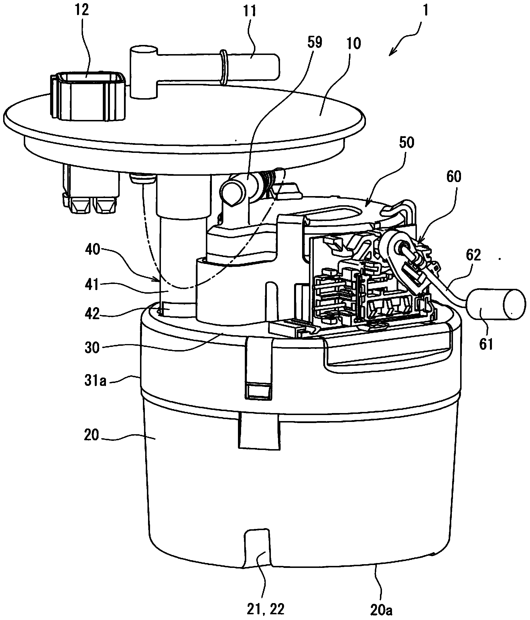
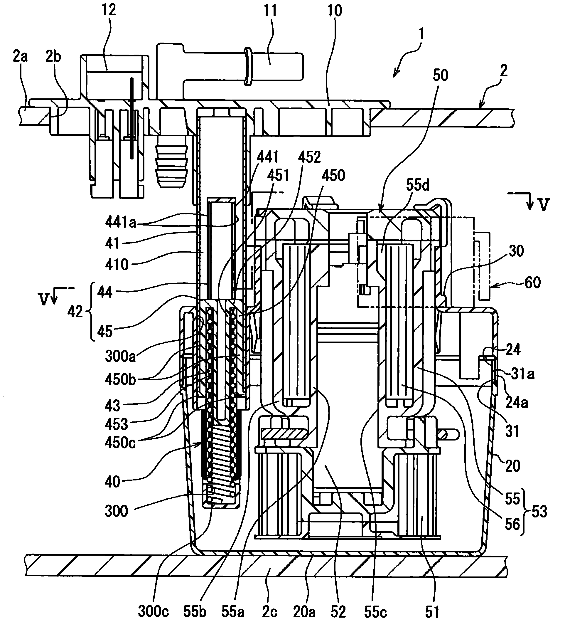
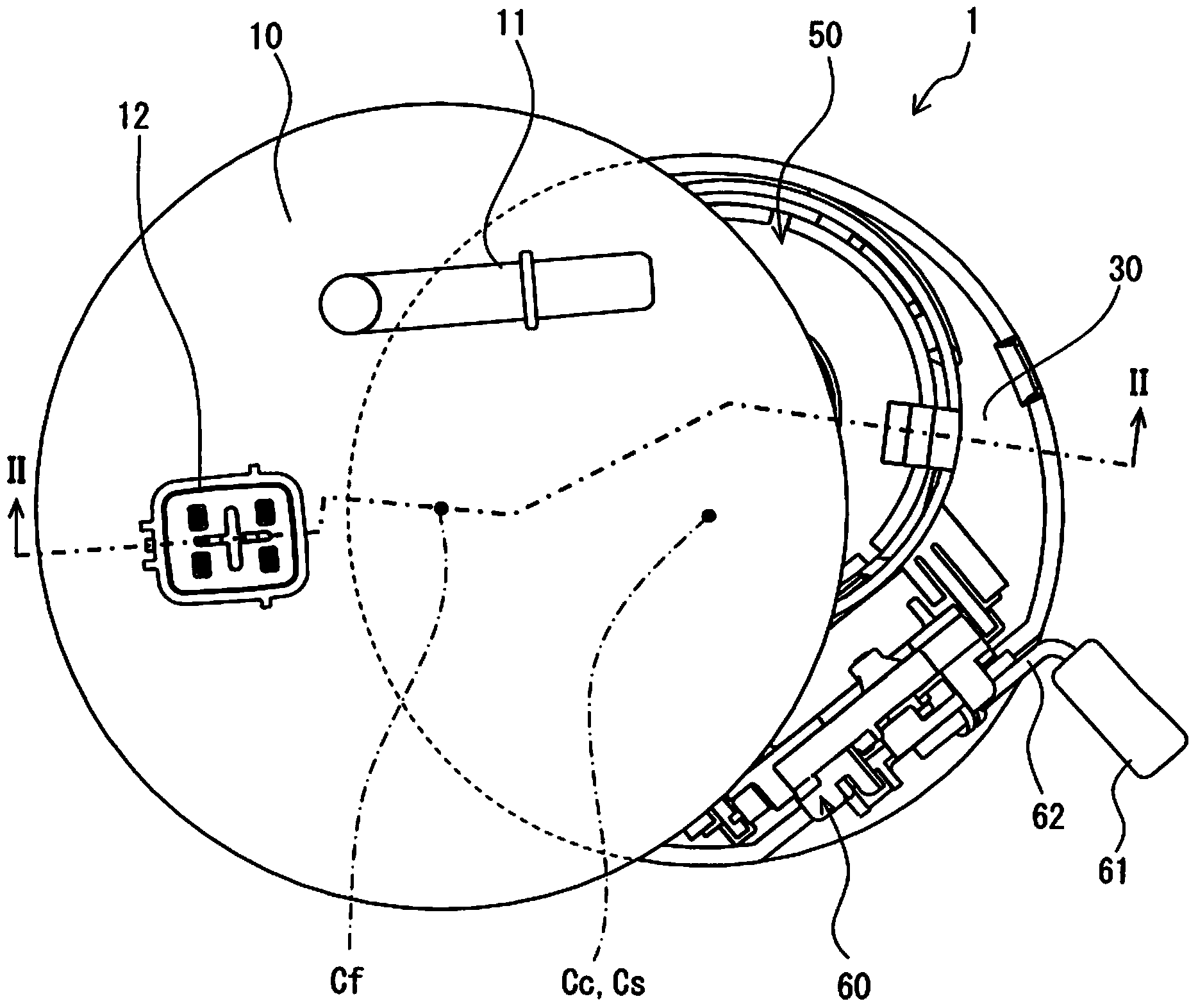
[0107] figure 1 and 2 The fuel supply device 1 of the first embodiment is shown. The fuel supply device 1 is attached to a fuel tank 2 of a vehicle (such as an automobile) and supplies fuel from the fuel tank 2 to the outside. The fuel supply apparatus 1 includes a flange 10 , a sub-tank 20 , a cover member 30 , an adjustment mechanism 40 , a pump device 50 and a remaining fuel amount detection device 60 . Such as figure 2 As shown, the above-mentioned components 20 , 30 , 40 , 50 , 60 of the fuel supply device 1 are put into predetermined positions in the fuel tank 2 except for the flange 10 . figure 2 The top-to-bottom direction of is substantially coincident with the vertical direction of a vehicle parked on level ground (horizontal plane).

[0108] Such as Figures 1 to 3 As shown, the flange 10 is ma...

no. 2 example )

[0136] The basic structure of a fuel supply apparatus according to a second embodiment of the present invention will now be described.

[0137] see Figure 11 , the second embodiment is an improvement of the first embodiment. The fuel supply apparatus 1001 of the second embodiment includes a flange 1010 , a sub-tank 1020 , a pump bracket 1030 , an adjustment mechanism 1040 , a pump device 1050 , a pressure regulator 1054 and a remaining fuel amount detection device 1060 . The above-mentioned components 1020 , 1030 , 1040 , 1050 , 1054 , 1060 in the fuel supply apparatus 1001 except for the flange 1010 are put into predetermined positions in the fuel tank 2 . Figure 11 The top-to-bottom direction of is substantially coincident with the vertical direction of a vehicle parked on level ground (horizontal plane).

[0138] see Figures 11 to 13, the flange 1010 made of resin material and designed as a disc body has a return pipe 1013 in addition to the fuel supply conduit 11 and...

no. 3 example )

[0160] A characteristic structure of a fuel supply apparatus according to a third embodiment of the present invention will now be described with reference to the drawings.

[0161] Such as Figure 16 and 17 As shown, the third embodiment is an improvement of the second embodiment. That is, according to the third embodiment, the ring gasket 1070 is added to the fuel supply device of the second embodiment.

[0162] In particular, the support shaft 1041 of the third embodiment is elongated in the axial direction as compared with the second embodiment to conform to the variation in the depth of the fuel tank 2 . Because of this change, an annular gasket 1070 made of resin material and designed as a cylindrical tubular body is inserted between the flange 1010 and the elastic member 1043 in the axial direction which is the same as the mounting direction of the support shaft 1041 to the flange 1010 coincide. Therefore, when adjusting the axial thickness (axial length) of the annu...


PUM


Abstract

The invention relates to a fuel supply device. A support shaft (41) is connected between a flange (10) and a pump device (50); a middle component (42) connected between the support shaft (41) and the pump device (50) is capable of allowing the relative position of the support shaft (41) and the pump device (50) to be changed in the axial direction; the middle component (42) restrains the relative position between the support shaft (41) and the pump device (50) in the circumferential direction of the support shaft (41) from being changed; and an elastic component (43) is received in the support shaft (41) and imposes restoring force in the axial direction of the support shaft (41) towards the bottom (2c) of a fuel box (2) to push the pump device (50) which is capable of moving relative to the support shaft (41) in the axial direction.

Description

[0001] This application is a divisional application of an invention patent application with the application number 201110276884.x, the application date being September 13, 2011, and the invention name being "fuel supply equipment". technical field [0002] The present invention relates to fuel supply equipment. Background technique [0003] In known fuel supply devices, a flange mounted to a fuel tank of a vehicle, such as a car, is connected to a pump device which is inserted into the fuel tank via a support shaft and pumps fuel out of the fuel tank. [0004] For example, Japanese Unexamined Patent Publication No. 2008-248801a discloses a fuel supply apparatus in which a flange is connected to a pump unit via a plurality of support shafts. When the flange is connected to the pump device at a plurality of positions via a plurality of support shafts respectively, it is possible to suppress deviation (positional deviation) generated at one installation position of the pump dev...

Claims


Application Information

Patent Timeline
Patent Type & Authority Applications(China)
IPC IPC(8): F02M37/10F02M37/00
Inventor 冈园哲郎及川忍小林清守林宣博野田真司森下浩松原一树丸山浩司井上正人大木浩伸
Owner DENSO CORP
Features
  • R&D
  • Intellectual Property
  • Life Sciences
  • Materials
  • Tech Scout
  • Unparalleled Data Quality
  • Higher Quality Content
  • 60% Fewer Hallucinations
Learn More