Soft element taking-out method and substrates separating method

A separation method and a flexible technology, applied in the field of semiconductor technology, to overcome the low removal rate and difficulty in mass production, improve the back-end process, and overcome the problem of precise alignment of components

Active Publication Date: 2014-06-11
HANNSTAR DISPLAY CORPORATION
View PDF8 Cites 5 Cited by
  • Summary
  • Abstract
  • Description
  • Claims
  • Application Information

AI Technical Summary

Problems solved by technology

[0004] In view of this, the embodiment of the present invention proposes a method for taking out flexible components. The flexible components are taken out after being prepared b

Method used


Image

  • Soft element taking-out method and substrates separating method
  • Soft element taking-out method and substrates separating method
  • Soft element taking-out method and substrates separating method

Examples


no. 1 example

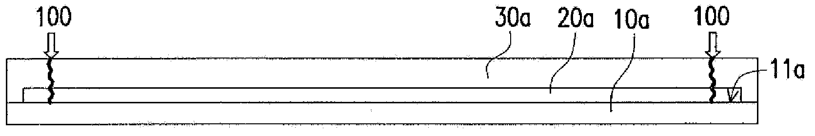
[0073] Figures 1A to 1F It is a schematic cross-sectional view of a method for taking out a flexible component according to the first embodiment of the present invention.

[0074] Please refer to Figure 1A , providing a first carrier 10a. The first release layer 20a and the first flexible substrate 30a are successively formed on the first surface 11a of the first carrier 10a, and all sides of the first release layer 20a and the first flexible substrate 30a have been formed at this moment. First pre-cut 100 . In one embodiment, the first flexible substrate 30a covers the first release layer 20a and the periphery of the first flexible substrate 30a is in contact with the first carrier 10a.

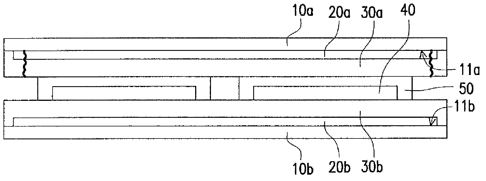
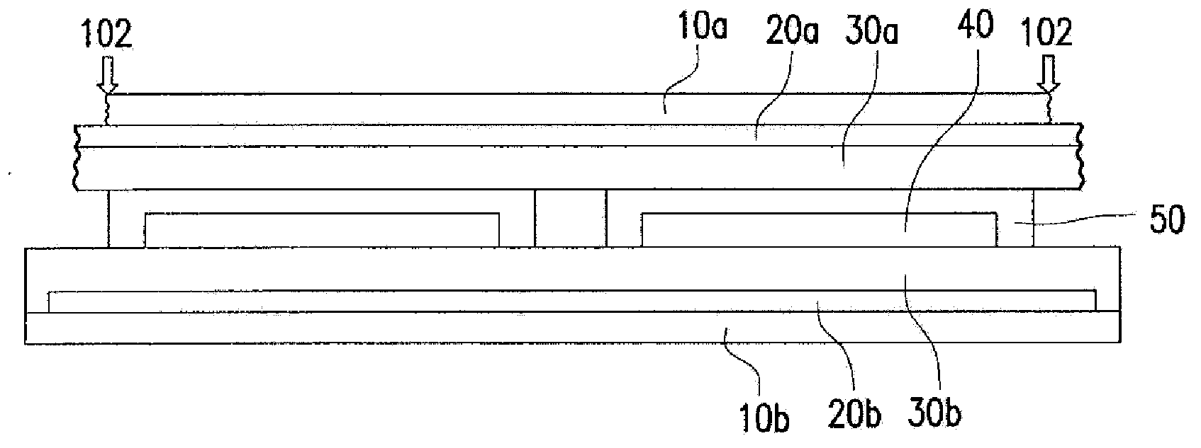
[0075] Please refer to Figure 1B , providing a second carrier 10b, a second release layer 20b, a second flexible substrate 30b and at least one flexible element 40 are sequentially formed on the first surface 11b of the second carrier 10b. In one embodiment, the second flexible substr...

no. 2 example

[0089] Figures 2A to 2G It is a schematic cross-sectional view of a method for taking out a flexible component according to the second embodiment of the present invention.

[0090] Please refer to Figure 2A , providing a first carrier 10c. A first release layer 20c and a first flexible substrate 30c are sequentially formed on the first surface 11c of the first carrier 10c. At this time, the first side (such as Figure 2A The first release layer 20c and the first flexible substrate 30c on the right side in ) have undergone first pre-cutting 200 . In one embodiment, the first flexible substrate 30c covers the first release layer 20c and the periphery of the first flexible substrate 30c is in contact with the first carrier 10c.

[0091] Please refer to Figure 2B , providing a second carrier 10d, a second release layer 20d, a second flexible substrate 30d and at least one flexible element 40 are sequentially formed on the first surface 11d of the second carrier 10d. In one...

no. 3 example

[0105] Figures 3A to 3C It is a schematic cross-sectional view of a method for taking out a flexible component according to a third embodiment of the present invention. The third embodiment is similar to the first embodiment, the difference is that the second flexible substrate 30b and the second carrier 10b of the first embodiment are separated by an existing method, while the first embodiment of the third embodiment The second flexible substrate 30b is separated from the second carrier 10b by the method of the present invention.

[0106] First, proceed Figure 1A to Figure 1E step, and then turn the whole group over so that it is upside down. In particular, in the step of providing the carrier 10b in the third embodiment, all sides of the second release layer 20b and the second flexible substrate 30b on the second carrier 10b have undergone second pre-cutting 300 (eg Figure 3A shown), but the first embodiment does not carry out the above-mentioned second pre-cutting st...


PUM

PropertyMeasurementUnit
Sizeaaaaaaaaaa

Abstract

Provided is a soft element taking-out method. The method comprises providing first support plates, the first surfaces of the first support plates are provided with first release areas, and first soft substrates are attached to the first release areas; the method also comprises providing second support plates, the first surfaces of the second support plates are provided with second release areas, and second soft substrates and at least one of soft element are successively attached to the second release areas; the method further comprises joining the first support plates and the second support plates and allowing the first surfaces of the first support plates to face the first surfaces of the second support plates; and the method comprises carrying out the first taking out step in which the first support plates are separated from the first soft substrates. The first taking out step at least comprises charging fluid into space between lower layers of two first support plates, so positive pressure is formed in the space. The invention also provides a substrates separating method.

Description

technical field [0001] The invention relates to a semiconductor process, and in particular to a method for taking out a flexible component and a method for separating substrates. Background technique [0002] In the electronic component industry, components are mainly prepared by a sheet-to-sheet method. The current practice is to stick the plastic substrate on the glass substrate first, and then perform the manufacturing steps of the flexible components on the plastic substrate. Although this method can meet the general process requirements, the problem that must be faced after the completion of the flexible component is how to smoothly remove the plastic substrate from the glass substrate. [0003] Therefore, the roll-to-roll (roll to roll) preparation method becomes another development direction. However, roll-to-roll technology still has many difficulties to be overcome. For example, it is not easy to achieve precise alignment of components in the roll-to-roll process...

Claims


Application Information

Patent Timeline
IPC IPC(8): H01L51/56H01L51/48
CPCY02E10/549H10K71/80
Inventor 施秉彝陈光荣彭依濠黄重颍叶树棠陈光中
Owner HANNSTAR DISPLAY CORPORATION
Why Eureka
Try Eureka